
Programmer’s Reference
Preface
GEM is an easy-to-use, visually oriented operating system. It was developed by Digital Research as an addition to the more traditional command-oriented operating systems, such as MS-DOS. In fact, the GEM literature from Digital Research refers to MS-DOS computers, and does not mention the ST’s system. Some find the standard GEM literature very difficult to follow when they are trying to program the ST.
It was with these facts in mind that we wrote this book. We cover many topics: the Atari Development Package; working with the editor and linker; using the C language compiler and the 68000 assembler; and finally, using the facilities of GEM. In short, the GEM Programmers Reference is an invaluable book for all ST programmers and developers.
Chapter 1 describes the basic structure of the GEM components—the Virtual Device Interface (VDI) and the Application Environment Services (AES).
Chapter 2 describes the different programming considerations using the high-level C language and 68000 assembly language. We introduce you to the features of the the Development Package and present a sample GEM program.
Chapter 3 focuses on the Virtual Device Interface, and Chapter 4 on the the Application Environment Services. Each function of the VDI and AES is thoroughly described so that you can use the enormous power of the GEM library routines. For every function we list the required parameters and any peculiarities to make your programming task easier.
At the end of Chapters 3 and 4 we present several sample programs. This is the most effective way of showing you how to use the GEM facilities. We hope that you will tailor these programs to you own needs.
In closing, we realize that GEM is a very complex system. Because of this, we’ve tried to carefully define our subject matter in as much detail as possible. Our goal is to pass onto you all the information that we’ve learned about the ST’s GEM operating system.
Best wishes—
Norbert Szczepanowski Bernd Gunther December, 1985
CHAPTER 1 -GEM ORGANIZATION IN THE ATARI ST
1.1 The Atari ST—An Ideal GEM Computer
GEM, or Graphics Environment Manager, is a graphics oriented operating system. Components are represented on the screens as small pictures known as icons. These icons can be manipulated to perform operating system functions such as displaying a disk directory, copying files or executing a program.
To handle all of these tasks, GEM requires a large amount of memory. To perform efficiently, GEM also requires a fast processor. The ST has both, making it a good candidate for the GEM operating system.
1.1.1 The Processor—Fast as Lightning
The Atari ST is a member of the 16-bit computer fraternity. The 68000 microprocessor, developed by Motorola in the late 70s, can put the earlier 8-bit microprocessor to shame. The 68000 microprocessor has a 16-bit-wide data bus, operates at a speed of 8 mHz, and has an addressable memory range of up to 16 megabytes. The 68000 instructions are very powerful, since 32-bit-register operations can be performed. As an example, the 8-bit 6502 chip transfers 4096 bytes in memory in about 65 milliseconds—but the 68000 only needs 6 milliseconds (that’s 11 times faster).
So, the 68000 is extremely well-suited to GEM. GEM is often responsible for handling up to several thousand graphics points on screen, and the ST is capable of doing this task quickly.
1.1.2 The Main Memory—Plenty of Room
The Atari ST has an enormous amount of working memory—512K. As we mentioned earlier, GEM is a graphics-oriented operating system, and as such, needs a lot of memory. One graphic “page” requires 32K, and that’s not even counting the program used to produce the page.
Another advantage of this large memory is the ability to hold several large data buffers, which lets you access several files concurrently and speed up the file access.
Last, but not least, the ST allows you to perform multi-tasking (running several programs at once).
1.1.3 Graphics—A Huge Matrix
GEM is invariably associated with graphics. Without high-resolution graphic capabilities, GEM is worthless. The ST, of course, has three modes of operation:
- 320 X 200 screen points, 16 colors
- 640 X 200 screen points, 4 colors
- 640 X 400 screen points, monochrome
The colors can be chosen from a palette consisting of 512 colors. The colors black and white are included in the 4- and 16-color modes.
GEM works in both 640 X 200 and 640 X 400 resolutions. The latter can only be used with a monochrome monitor, though.
1.2 GEM Structure
A general introduction to GEM is in order, before we do any programming. GEM is made up of two major subsystems:
- VDI (Virtual Device Interface)
- AES (Application Environment System)
AES and VDI are nothing more than libraries (along the lines of the Library of Congress) of functions and program routines. These routines are integrated into your programs, and connected to it when compiling or assembling. We’ll discuss usage of these functions later, in the section on programming in the C language.
The VDI contains all the essential graphic functions (drawing lines, circles, etc.).
The functions for windows, boxes and such are contained in the AES section. AES has a lower priority than the VDI, and VDI has a lower priority than the DOS. This hierarchy is:
- DOS (Disk Operating System)
- VDI (Virtual Device Interface)
- AES (Application Environment System)
1.2.1 GEM—VDI
1.2.1.1 VDI Architecture
The purpose of the VDI is to make graphic programming simpler for the user. The trick used here is to make the use of the graphic functions independent of the graphic output device. A VDI component, the device driver, concerns itself with device-specific operations. VDI has the following logical components:
• GDOS (Graphic Device Operating System) • GIOS (Graphics Input/Output System) w/ device driver • Metafiles
VDI also allows for different hardware configurations within GDOS. This has valuable advantages, as we’ll soon find out.
1.2.1.2 GDOS (Graphic Device Operating System)
The GDOS contains all device-independent functions. This means that a programmer can write a C program on one computer (for example an IBM PC) that will run on the ST. Furthermore, the programmer can use the GDOS to access virtually any type of disk drive, regardless of brand.
With the GDOS, the device-independent functions provide for two types of coordinates:
- NDC (Normalized Device Coordinates)
- RC (Raster Coordinates)
The normal device coordinates range from 0,0 (lower left-hand corner) to 32767,32767 (upper right-hand corner). While not all of these points are usable on present devices, GEM is designed for the future with upward compatibility to more advanced graphic capabilities.
The raster coordinates begin in the upper left-hand corner (0,0) and end in the lower right-hand corner, which is (640,400) in the maximum (monochrome) graphic mode.
1.2.1.3 GIOS (Graphic Input/Output System)
As the title says, the GIOS is GEM’s input/output system, containing all device-specific I/O functions for devices connected with the ST. The programmer does not talk directly to the GIOS. All graphic functions are routed by GDOS to the GIOS which then performs the appropriate function.
GIOS is the interface between GDOS and input/output devices.
For each device connected, the GIOS has a device driver. A graphic application can be adapted easily for a new input/output device by supplying a new device driver.
GDOS loads the needed device driver into memory. The application can work with every device that has a driver residing in memory.
1.2.1.4 The Metafile
All graphic output can be written as a standardized file called a Metafile. A Metafile can be read and updated by any application. With Metafiles, it’s possible to combine graphics from GEM DRAW with text from the word processor GEM WRITE. In short, you have the ability to move graphics to any other application.
1.2.2 GEM—AES
1.2.2.1 AES Architecture
AES stands for Application Environment System. This “environment” is graphic-oriented in GEM. Communication between user and computer is performed by “manipulating” graphic elements (e.g., windows and icons). The graphic environment is an especially powerful operating system, made up of several components.
The Routine Library can be used to access all elements of the AES. Multi-tasking makes it possible to run several applications simultaneously. The Shell represents the operating system itself (TOS). Choice of screen elements makes it possible to temporarily store graphic pages.
1.2.2.2 The Routine Library
The routine library contains all of the AES function calls, such as those that move graphic objects, read the mouse, monitor windows, etc.
The library is stored in ROM in the Atari ST (early versions of the ST may not have a ROM-based library). The Atari Development Package also contains a set of C routines. A proposed set of Pascal routines may soon be available.
1.2.2.3 Multi-tasking
Multi-tasking allows processes to run simultaneously. The Atari ST is limited to the following processes:
- one application
- three desk-accessory programs with a maximum of six desk accessories (utilities, such as a calculator) or six background processes
- AES screen manager
1.2.2.4 The SHELL
The Shell switches between graphic applications and text applications. It also acts as an interface to the operating system. It can activate the TOS command set and supply commands.
1.2.2.5 The Buffer
The Desk Accessory Buffer contains the program codes of the desk accessories, which are permanently available. It includes a buffer that supports the graphic functions. For example, as soon as the user picks an area containing a menu screen, the menu is saved into a buffer. If the menu is needed again, the AES can automatically reconstruct the screen from this buffer.
CHAPTER 2 - Programming with GEM
2.1 Programming Languages
GEM lets you work with either of two main programming languages: C or Assembler. Both languages have advantages and disadvantages. Here is a short overview:
| Feature | C | Assembler |
|---|---|---|
| Execution Speed | + | |
| Program Length | + | |
| Readability | + | |
| Error Checking | + | |
| Portability | + |
Choosing a language is really up to you; have a good look at the criteria, and decide which one would best fit your applications. For example, a fast graphics program would be best written in assembly language. The disadvantage here is that this program will only run quickly on another system using the same processor. Such a program might be comparable to an IBM’s. But a program written in C would be compatible and easily transportable to an IBM PC, for example.
Then again, most C compilers can produce efficient assembler code.
GEM itself is written in C.
2.2 A Short Introduction to C
C is an all-purpose programming language, with speed that compares favorably to the speed of machine language. C was originally used for operating system program development. The UNIX operating system was written in C. However, C is also a fine language for writing databases and word processing applications.
C is like machine code in the sense that characters, numbers and addresses are used, but it has no parallels with BASIC or COBOL. Because of its relatively concise set of statements, it is difficult to work with complete character strings or arrays in C.
The standard set of C statements has no I/O operations like READ or WRITE. These operations have to be implemented through the function library (a collection of computer dependent routines with standard calls).
The omission of these language elements really puts C at a great disadvantage. But this is an advantage for many programmers—thanks to its small command set, C is a relatively simple language to learn. Also, and perhaps more importantly, most computers have compatible versions of C, so the language is extremely portable.
C has all the important control structures like subroutines, loops and interrupt criteria. Furthermore, it uses address arithmetic and pointer values. Functions that cannot be changed are given as arguments. Like Pascal, C also has recursive functions that can be recalled at any time. C is a highly effective language for a huge spectrum of applications. The following section will introduce the fundamentals of the C language.
2.2.1 A Simple C Program
Learning a language requires you to learn its elements, as well as the proper and most efficient “grammar”. This short program will illustrate the fundamentals of C. It prints the word ATARI on the screen:
/* Program Name: FIRST.C */
main ()
{
    printf ("ATARI\n");
}
C programs are basically composed of one or more functions. The function main() is, as its name implies, the main function. It must be included in every C program. Parameters may be paired to all functions by enclosing them in parentheses. Function identifiers must be followed by a set of parentheses even if no parameters are required.
A function is composed of one or more statements. These statements are delimited by brackets ({}). The brackets are equivalent to Pascal’s BEGIN and END commands. Outputting text is performed by the standard C function printf, which is not in the normal C language set. Instead, printf is in the standard I/O (Input/Output) library.
The function argument for printf is “ATARI\n” in our example. The characters \n are C’s way of saying <RETURN>.
Every statement is ended with a semicolon.
2.2.2 Compiling a Simple Program
Try the following examples out on your ST. To make the transition to C easier for you, detailed comments will accompany every example.
The diskettes in your development package should include the EDITOR diskette, the COMPILER diskette, and the LINKER diskette. The program is written using the EDITOR.
The Mince editor program was used for all the examples in this book. The most important editing commands of the Mince editor are:
|Key combination | Action | |–|–| |CONTROL-X, CONTROL-R | Read a file| |CONTROL-X, CONTROL-W | Save file, enter file name| |CONTROL-X, CONTROL-S | Save current file| |CONTROL-X, CONTROL-C | Exit editor|
When you save a C source file, be sure to add a .C extension (e.g. FIRSTC.C).
On a one drive system, save the source program (FIRSTC.C) directly to the compiler disk. To start the compiler select the program BATCH.TTP. An input box appears, and you should enter:
C filename
For example, typing in C FIRSTC compiles the file FIRSTC.C. Notice that you do not enter the .C extension of the filename. After compiling, the temporary work files are erased, and an object module is written to the disk. This module has the extension .O (e.g. FIRSTC.O), and is then copied to the linker diskette (with a single drive system).
Check to see if the file LINKTOS.BAT is on the linker disk. If not, type in the following general-purpose batch file with the editor, and save it with the name LINKGEN.BAT:
link68 [u] %1.68k=gemstart,%1,vdbind,osbind,aesbind,libf,gemlib
reldmod %1
rm %1.68k
wait
Start the linker by selecting the BATCH.TTP program from the linker disk. At the input window enter:
LINKGEN filename
To link FIRSTC.O, type FIRSTC for the filename. Don’t include the extension .O. The linking procedure will start, and produce an executable program with the extension .PRG. See Chapter 2.5 for details on these items.
2.2.3 Variables and Loop Structures
The next sample C program gives the sum of the numbers from 1 to 100.
/* Output of sum of numbers from 1 to 100 */
/* Program Name: SUMC.C */

main ()
{
    int number, sum;

    number = 1;
    sum = 0;

    while (number <= 100)
    {
    sum = sum + number;
    number = number + 1;
    }
    printf ("%d\n", sum);
    gemdos(0x1); /* wait for keypress */
}
Note the presence of main(), as well as our opening comments (always written between /* …. */). Comments can be placed almost anywhere in a program. A good place is after the semicolon at the end of the line described. Comments make programs much more readable and informative.
Note that within the first set of brackets, the local variables are defined. The declaration int specifies a 16-bit integer number between -32768 and +32767. Both number and sum are declared as 16-bit integers.
Along with int are the other C data types:
| type | description |
|---|---|
| float | floating-point variables with mantissa and exponents |
| char | a single character |
| short | an 8-bit whole number |
| long | a 32-bit whole number |
| double | a floating-point number with doubled accuracy |
After variable definition follows the assignment statements. This assigns a starting value to each variable:
number = 1;
sum = 0;
Variables aren’t automatically set to zero, and may contain a random number.
The while statement is used to calculate the sums. An expression following a while statement is enclosed in parentheses. The while statement loops until the expression becomes false or zero.
The statements within a while loop will normally be the program itself (this is good to know). During every iteration of the loop, the value of number is added to sum and the value of number is raised by one. Incrementing number can also be accomplished in C like this:
number++
Double plus-signs (++) raise the value of the variable by one. Both loop statements can be used:
sum = sum + number;
number++;
Simpler still:
sum = sum+ number++;
The above statement will increment number after the addition. The statement:
sum = sum + ++number
Increments number before adding it to sum.
Decrementing numbers (decreasing the variable by one) is just as simple as incrementing:
number-- or --number
This is identical to number = number - 1.
Finally the program prints the final sum to the screen. The function to do this is printf. The character sequence %d is a format specification and means that the variable to be printed is a whole decimal number (integer). C gives us other format specifications as well:
|sequence|description|
|-|-|
|%f | print floating point number|
|%x | print unsigned hexadecimal number|
|%o | print unsigned octal number|
|%c | print a single character|
|%s | print a character string|
Floating-point variables allow us to represent numbers with decimal points and digits to the right of that point. The format element %4.2f describes a number with four digits, with two decimal places (e.g. 34.45, 23.76).
The function gemdos(0x1) is a GEMDOS call. This function waits for input from the keyboard.
Besides while, the C language has another loop structure. It contains the starting number, loop operation and condition all on the same line. Here’s a sample program for this type of loop:
/*Output of the sum of numbers between 1 and 100 */
/* Program name: SUM2.C */

main ()
{
    int number, sum;
    for (number=1; number <= 100; number++)
        sum = sum + number;
    printf ("%d\n", sum);
    gemdos(0x1);
}
The for loop contains three arguments, each separated by a semicolon. The first argument is executed once, and is the initial setting of the control variable:
number=0
The second argument is the condition that controls the end of the loop:
number <= 100
The last argument is the repeating assignment that is performed during each iteration of the loop body:
number++
The addition sum = sum + number can also be put in the third argument in a for loop:
/* Output of the sum of numbers from 1 to 100 */
/* Program name: SUM3.C */

main()
{
    int number, sum;

    for (number=1; number <= 100;
            sum = sum + number++);

    printf ("%d\n", sum);
    gemdos (0x1);
}
The loop structure used depends on the situation.
2.2.4 Symbolic Constants
Constants can be defined symbolically and given values. To assign a value to the symbol, the #define statement is used. All symbolic definitions are placed at the beginning of the program. Let’s revise our original program slightly:
/* Output of the sum of numbers from 1 to 100 */
/* Program name:SUM4.C */
main()
#define MAX 100

{
    int number, sum;
    for (number=1; number <= MAX;
            sum = sum + number++);
    printf ("%d\n", sum);
    gemdos(0x1);
}
You aren’t limited to defining numerical constants—you can even define character strings:
/* Output of sums of numbers from 1 to 100 */
/* Program name: SUM5.C */
main()
#define MAX 100
#define RET \n

{
    int number, sum;

    for (number=1; number <= MAX;
            sum = sum + number++);

    printf ("%d'RET'", sum);
    gemdos(0x1);
}
Now the carriage return \n is represented by the symbolic name RET.
Notice that a semicolon does not follow the #define statement.
2.2.5 Functions
A function in C is equivalent to a subroutine in BASIC, a function in Fortran, and procedures in COBOL, PL/I or Pascal. Function calls are the best method of arranging complex programs. In general, the more functions in a program, the more clearly it is arranged. The statement main() is basically just a function call.
The following program prints the third power for the numbers 1 to 100:
/* Third power of numbers 1 to 100 */
/* Program name: THIRDC.C */
main()    /*main program which calls pot function*/
{
    int i;
    long pot();

    for (i=1; i <= 100; i++)
        printf("%d %ld\n", i, pot(i));

    gemdos(0x1);
}

long pot(n)    /* n to third power function */
int n;
{
    long x;
    x = n * n * n;
    return (x);
}
This program can be stated a bit more eloquently, we used this sample only to give you a general demonstration of a function.
All functions are built on the same principle:
Name (parameter list)
Parameter declarations
{
    /*function body starts here*/
    Declarations
    Statements
}
The parameter list can be skipped when a function has no parameters. The parameter declaration (variable definition) is given before the body of the function.
The argument used by the function must be declared within the function definition to indicate the function’s data type. The function itself occurs within brackets. Next, the local variables of the function are declared.
Note: In contrast with other languages, the function called cannot alter the variables of the calling function called.
The function can return a result to the called function. This result can be placed in the variables by using the return() command, and must have been declared in the function as a local variable. Our example uses the variable x. If no result is given, return() would be used.
2.2.6 Conditions
One of the fundamental structures of a programming language is the condition. For example:
/* Print primary numbers from 2 to 10000 */
/* Runtime: approx. 3 minutes 45 seconds */
/* Program name: PRIMEC.C */

main()
{
    int i, n;
    for (n = 2; n <= 10000; ++n)
    {
        for (i = 2; i < n; ++i)
            if (n % i == 0)
                break; /* no prime number */
        if (i == n)
            printf("%d\n", n); /* output */
    }
    gemdos(0x1);
}
The first loop declares the starting and ending point of the loop (2 to 1000). The second loop tests for the existence of a prime number at the moment—if (n % i == 0). A conditional must be enclosed in parentheses. The two equal signs set up equality between one and the other condition. The operation n % i finds the integer remainder of both variables after division. When the remainder is 0, then it is not handled as a prime number. The loop is left with the break statement.
The next conditional i==n tests only whether all the numbers are smaller than the number in the first condition. If so, the number is displayed with the printf function.
Here are all the comparative operations:
| Operator | Description |
|---|---|
| < | Less than |
| <= | Less than or equal |
| > | Greater than |
| >= | Greater than or equal |
| == | Equal |
| != | Not Equal |
Congratulations—you’ve just learned the essentials of C. There are many books on the C language. We recommend that you get one to find out more details of C, while we move on to other topics.
2.3 A Short Introduction to the Assembler
This chapter will briefly explore assembly language on the ST, and includes several sample programs.
The advantages of assembly language over a higher-level language are that assembly language programs execute at a higher speed and use less memory. Its disadvantages are that it is tedious work, difficult to read and debug, and very seldom transportable (easily moved from computer to computer). With the ST’s 512K of memory, the fast disk drive, and the overlay techniques available, your life might be a little simpler if you avoided assembly language (also called machine language) programming.
For all its drawbacks, machine code is the most efficient language to use. And, in the long run, 68000 assembly language really isn’t that much harder to use than C.
2.3.1 The 68000 Processor
The 68000 has 8 data registers that contain the operands for the different operations. Each register is 32 bits (4 bytes) wide. The diagram below illustrates the layout of a data register, where the the most significant bit is leftmost. The data registers are numbered from D0 to D7.
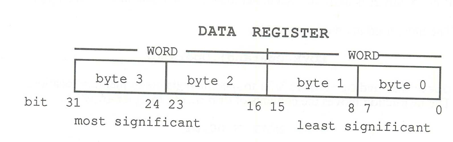
The 68000 has 8 address registers numbered from A0 to A7. It is possible to access memory locations directly with the address register, but you’re not limited to this. We shall discuss the different types of addresses later. Each address register is 32 bits long, but only 24 bits of each are used for addressing. In addition, every address register can be used as a stack pointer. Address register A7 is the stack pointer used by the processor in subroutine calls.
The 68000 has two working modes: user mode (normally on) and supervisor mode. Supervisor mode has its own stack pointer.
Like any other microprocessor, the 68000 has a status register, which informs you of what the system is up to. The most significant byte of the 16-bit-wide registers contains system information, while the least significant byte stores program conditions (e.g. overflows).
2.3.2 Important Assembler Instructions
We will only touch on the most important of the assembler’s large instruction set. Almost all the instructions used in 8-bit programming are used here. If you’ve done machine language programming before, most of this will be review material.
On the 68000, almost all instructions can have 32-bit-long operands, although you can still use 16- or even 8-bit operands. Sometimes operand lengths are variable in an instruction. There are three identifiers used to tell the assembler the instruction length:
.B- 8 bits (byte).W- 16 bits (word).L- 32 bits (longword)
If no identifier is used, the assembler assumes the operand is 16 bits long.
The most-used instruction is MOVE:
MOVE Operand1, Operand2
Operand1 and Operand2 refer to specific registers or memory locations. The instruction moves the contents of Operand1 to Operand2.
MOVE.W D0, D1
The above example moves the least significant 16 bits from data register D0 to data register D1. The first operand is the source, the second the destination. This sequence is used for all instructions.
Another useful instruction is the addition instruction:
ADD.W D0,D1
The contents of D0 and D1 are added together, and the result is placed in D1. What happens, though, if we add $FFFF and $0001 (both 16-bit numbers)? The result would be $10000, and is 1 bit longer than ADD.W can handle. The processor sets an additional bit when this happens; which bit set depends on the situation and conditions. This bit is found (among others) in the user byte of the status register.
User-Byte of Status Register
Bits:
| 7 | 6 | 5 | 4 | 3 | 2 | 1 | 0 |
|---|---|---|---|---|---|---|---|
| X | N | Z | V | C |
C-Flag (Carry)
If a carry occurs as a result of an arithmetic operation, this bit is set. SHIFT and ROTATE instructions use this bit as temporary storage space.
V-Flag (Overflow)
The V-flag is set when an overflow occurs.
Z-Flag (Zero)
The Z-flag is set when an arithmetic operation has a zero input. This happens when memory locations and/or registers beneath one another are compared and found equal.
N-Flag (Negative)
A negative result sets this bit. It, too, is used in comparisons.
X-Flag (Extend)
This has the same function in principle as the C-flag, but this bit affects fewer instructions.
The main purpose of the flags is to alter the sequence of program execution according to the current status of the processor. The branch instruction is used to alter the sequence of program execution.
Branch instructions can be divided into three categories:
1) Branches depending on flag status - BCC/ carry cleared - BCS/ carry set - BNE/ zero cleared - BEQ/ zero set - BVC/ overflow cleared - BVS/ overflow set - BPL/ negative cleared - BMI/ negative set 2) Branches after unsigned comparison - BHI/ greater than - BHS/ greater than or equal to - BLO/ less than - BLS/ less than or equal to - BEQ/ equal - BNE/ unequal 3) Branches after signed comparison - BGT/ greater than - BGE/ greater than or equal to - BLT/ less than - BLE/ less than or equal to - BEQ/ equal - BNE/ unequal
Categories 2 and 3 are branches that follow comparisons. For the moment, we’ll concentrate on the first group.
In practice, using branch instructions would look like this:
ADD     D0,D1
BCS     label_1 ;If result too large, goto label_1
* ...
* ...
* ...
Label_1 ;e.g., error output
When two values are compared, the system distinguishes between numbers with leading characters and those without (e.g. 3000 and -3000). This comparison is accomplished by the CMP instruction:
CMP     D0,D1
BHI     label_2 ; branch if D1 is more than D0
* ...
* ...
* ...
Label_1
* ...
The second (destination) operand is compared with the first (source) operand; the sequence of operands is very important. There is also another branch instruction— BRA (Branch Always). The BRA instruction will branch regardless of flag conditions or the results of comparisons.
If you’re accustomed to programming in high-level languages, you already know about loop programming. Thanks to the DB command, you can use loops in assembly language. DB will cause a jump to a loop under certain conditions.
MOVE    #7,D0 ; eight iterations
Loop.         ; This section will be repeatedly executed
* ...
* ...
DBF     D0, Loop
Break conditions can be given using the branch instructions. In addition, you have available the instructions DBF (no break) and DBT (always break):
- DBT/ always break
- DBF/ no break
- DBHI/ greater than
- DBLS/ less than or equal to
- DBCC/ carry cleared
- DBCS/ carry set
- DBNE/ unequal
- DBEQ/ equal
- DBVC/ overflow cleared
- DBVS/ overflow set
- DBPL/ positive result
- DBMI/ negative result
- DBGE/ greater than or equal to
- DBLT/ less than
- DBGT/ greater than
- DBLE/ less than or equal to
We mentioned the unconditional branch instruction BRA a few paragraphs ago. This instruction can only branch within about 32000 bytes in either direction. Larger branches must be accomplished using JMP (jump):
JMP Label_3 ; goto Label_3
Frequently used program sections can be separated into subprograms or subroutines. Each time the subroutine is needed, a JSR (jump to subroutine) is called. On reaching the RTS instruction in the subroutine (return from subroutine), the main program picks up where it left off.
JSR     subprogram              ; call subroutine
*       the main program will
*       executing here once the
*       subroutine is finished
JSR     subprogram              ; call it again
.
.
subprogram
*       instructions of
*       the subroutine here
RTS                             ; go back to main program section
Another useful instruction in GEM is the TRAP instruction. The operand of the T`RAP instruction should have a number between 0 and 15; this number selects a certain routine, rather than an address.
TRAP #1 ; call for GEM handler
2.3.3 Addressing Modes on the 68000
The 68000 has a variety of addressing modes. An addressing mode is the means by which the address of one of the operands is calculated in that instruction’s operand. Below are the different addressing modes:
1) Immediate addressing
In this addressing mode, the data is specified as part of the instruction:
MOVE #30,D6
The above instruction immediately loads the decimal number 30 into data register 6.
2) Absolute long/short addressing
In this addressing mode, the memory location containing the data is specified as part of the instruction:
MOVE $FF7795,D6
The contents of memory location $FF7795 are transferred to data register 6.
If the memory location lies in the range $000000-$07FFFF or $FF8000-$FFFFFF, then a special form of the instruction called short addressing is used. The advantage is that the length of the instruction is reduced by two bytes.
The assembler can distinguish between the two addressing modes, and will act accordingly.
3) Indirect addressing
In this addressing mode, the address of the data is specified in a register:
MOVE (A0), D5
The contents of memory location contained in address register A0 are copied into data register D5.
4) Indirect addressing with displacement
In this addressing mode, a constant value (displacement) is added to the contents of the register. The sum of these is the effective address of the data:
MOVE D1, 10(A5)
The contents of data register D1 are copied to the memory location whose address is the sum of 10 and the contents of address register A5.
5) Indirect indexed addressing with displacement
One disadvantage of indirect addressing with displacement is that the displacement is always a constant value. In this addressing mode, we can get around this limitation by adding the contents of an additonal data or address register to produce the effective address:
MOVE D0, 20 (A2, D0)
If A2=500 and D0=100, D0 results in the following:
| 500 |
| +100 |
| +20 |
| = 620 |
In simple indexed addressing (without offset), the displacement is zero.
6) Pre-decrement addressing
This addressing mode is similar to indirect addressing, only the value of the given address registers includes a decrement value (1, 2 or 4 bytes):
MOVE D2,-(A7)
The contents of data register D2 are copied to the memory location specified by address register A7 before address register A7 is decremented by one.
7) Post-increment addressing
This addressing mode performs the exact opposite operation of pre-decrement addressing. The value of a register’s contents are incremented by 1 after the operation is performed.
The two addressing modes (pre-decrement and post-increment) are useful for maintaining stacks. A stack is created with pre-decrement mode, and can be accessed with post-increment mode.
MODE    D0,-(A7) **put 2 values on the stack
MOVE    D1,-(A7)
* ...
* ...
* ...
MOVE    (A7)+,D1 ** get values from stack
MOVE    (A7)+,D0
8) Relative program counter addressing with offset
In this addressing mode, displacement is added to the contents of the program counter (PC) to produce an effective address:
CLR 10(PC)
The constant value 10 is added to the contents of the program counter to yield an effective address. This memory location is cleared (zeroed).
9) Relative program counter addressing with indexing and offset
This addressing mode is rarely used. It is similar to 5) Indirect indexed addressing with displacement, except that the PC is substituted for the address register.
2.4 The ST Development Package
The ST Development Package consists of 7 diskettes and 2000 pages of documentation. This serves as a starting place for developing GEM applications. The diskettes contain the following:
The TOS Disk
TOS.IMG GEM Desktop, AES, VDI, GEMDOS and BIOS DESK1.ACC VT52 Terminal Emulator DESK2.ACC Control panel
The Language Disk
LOGO.PRG LOGO-Interpreter LOGO.RSC LOGO-resource file ANIMAL.LOG Example program KNOWN.LOG Data for ANIMAL.LOG
The MINCE Editor Disk*
PRGINTRO.DOC Introduction to MINCE editor LESSON4.DOC LESSON6.DOC LESSON8.DOC MINCE.PRG the editor MINCE.SWP MINCE overlay CONFIG.PRG
*New versions of the package may have a different editor
The Compiler Disk
CP68.PRG 3-pass C-compiler CO68.PRG C168.PRG
AS68.prg 68000 Assembler AS68INIT AS68SYMB.DAT
BATCH.TTP Batch processing program RM.PRG Program to delete files
WAIT.PRG Return to desktop program C.BAT Compile batch file
DEFINE.H Type definitions GEMBIND.H Gem binding kit GEMDEFS.H Common GEM definitions VDIBIND.H External VDI functions TOSDEFS.H TOS file attributes / error definitions
OBDEFS.H GEM object definitions OSBIND.H For binding GEM and BIOS PORTAB.H Files for porting IBM applications MACHINE.H TADDR.H
The Linker disk
LINK68.PRG Linker program RELMOD.PRG Relocation program BATCH.TTP Program for batch files RM.PRG Program to delete files
WAIT.PRG Return to desktop program LINKAP.BAT Linker batch file for applications LINKACC.BAT Linker batch file for accessories
| Command Line Interpreter | Description |
|---|---|
| COMMAND.PRG | Command line interpreter |
| DUMP.PRG | Hex-file print |
| FIND.PRG | find string |
| HIGH.PRG | Medium res. program |
| LOW.PRG | Low-res program |
| KERMIT.PRG | file transfer program |
| NM68.PRG | symbol table print program |
| AR68.PRG | Library creation utility |
| SID.PRG | Debugger |
| SIZE.PRG | Program segment size utility |
| APSTART.S | Source to application start routine |
| ACCSTART.S | Source to accessory start |
| ACSKEL.C | Example accessory |
| APSKEL.C | Example application |
| Resource Construction Set | Description |
|---|---|
| RCS.PRG | Resource Construction Set |
| RCS.RSC | RCS resource file |
| DOODLE.PRG | Example application |
| DOODLE.RSC | Doodle resource |
| DOODLE.C | Doodle C definitions |
| DOODLE.H | Doodle header file |
| DOODLE.DEF | Resource definitions |
The following pages contain an overview of the development package needed for GEM program development.
2.4.1 The Editor
The editor is the program that allows you to write and edit source programs to be compiled. You can also create batch files with this editor.
The editor included in the development package is MINCE (later versions of the development package may contain a different editor).
MINCE.PRG is the editor program itself. It is started like all other applications, but it isn’t a GEM application; it runs under the TOS applications (Menu Options). On every boot-up, it’s wise to install it as a TOS application. Thus, you install the MINCE.PRG from the menu OPTIONS with TOS-takes parameters (TTP) or you can rename the program to MINCE.TTP from the FILE menu with SHOW Info….
CONFIG.PRG is a program for adapting the editor to the computer. All details of the keyboard, screen and other compatibility factors are kept here, but is redundant, since MINCE is adapted specifically for the ST. MINCE.SWP is the Atari ST configuration data.
LESSONS are text files that can be read into the editor. They give instructions on use of the MINCE editor.
Here are some editor basics. Start the editor; you can now input a program.
To save the program as a file, press the key combination Control-X/Control-W after you give it a name. If the program file is to be compiled with the C compiler, add the suffix .C (e.g. TEST.C).
To read a previously created file, press the key combination Control-X/Control-R). After making any changes to this file, you can resize the file without entering a new filename by pressing Control-X/Control-S.
To exit the MINCE editor, press Control-X/Control-C.
The list below gives your the most important MINCE commands. The Control key is represented by the character ©.
©-A Start-of-line ©-D Delete line ©-J New line ©-T Exchange character ©-X ©-S Save file ©-X ©-C Exit editor ©-E Goto end-of-line ©-K Delete line ©-X ©-R Read file ©-X ©-W Rename & save file
2.4.2 The Compiler
The development package contains a C-compiler from Digital Research. In addition to the compiler program, there are several other programs on the compiler disk:
CP68.PRG, C068.PRG and C168.PRG are part of the three-pass compiler. Sourcefiles are compiled in three steps. Programs are compiled by calling the C.BAT file, which is called from the BATCH.TTP program. (TTP means TOS Takes Parameters, and allows you to input the filename).
The compiler steps cannot be executed individually. The batch program C.BAT automatically runs them. If this batch file isn’t on your compiler disk, type the following lines using the editor, and save it on your compiler disk with the name C.BAT:
cp68 %1.c %1.1 co68 %1.i %1.1 %1.2 %1.3 -f c168 %1.1 %1.2 %1.s rm %1.1 rm %1.2 as68 -1 -u %1.s rm %1.s wait.prg
The program rm is necessary to delete the work files. The temporary work files are deleted so they do not clutter the disk. If the assembler source file is needed, remove the line rm %1.s from the C.BAT file.
The wait.prg program waits after the compiling procedure, until
The BATCH.TTP program starts a procedure which brings up the batch files to be run. On the OPEN APPLICATION command line enter:
C name
C is the name of the batch file to be called, and name is the program to be compiled. Do not enter the .C suffix, because it’s included in the C.BAT file. The %1 in the C.BAT file is the place-holder for the filename parameter.
The actual programs of the C compiler are described below:
1) The C P68 Preprocessor
The preprocessor connects the source file to any header file specified by #include, and sets up needed symbols specified by #define. The preprocessor is called as follows:
C P68 file.C file.i
file.C is the source file and file.i the new resulting source file.
2) The C O68 Parser
The parser produces an “intermediate compiled code” from the file created by the preprocessor. The parser is called with:
C O68 file.i file.1 file.2 file.3 -f
3) The C I68 Code Generator
The code generator creates an assembler source file from the intermediate file.
C I68 file.1 file.2 file.s
File.s is the assembler source file. File.1 and file.2 are work files.
The compiler does not create “ready-to-run” object files. Instead it creates assembler source files. This has advantages: it’s easier to find errors, and makes programs more efficient using assembler files. The assembler source file contains the corresponding C source lines, as described on the next page.
The Assembler Source File
The assembler source file is processed with the assembler found on the compiler disk. It is called like this:
AS68 -l -u file.s
The parameter -l states that all addresses will be handled in 32-bit form. The parameter -u declares that all unknown symbols are to be treated as external variables.
The assembler produces the object file, file.o, which has to be linked together with the various operating system files using the linker disk at a later time.
Next we’ll describe the assembler, and then discuss the linker.
2.4.3 The 68000 Assembler
If you want to run the assembler seperately from the C compiler, you’ll have to install the application AS68 to TOS-takes parameters from the desktop menus Options/Install Applications. As the AS68 starts with a double-click on the mouse, you enter the following options in the OPEN APPLICATION window’s command line:
[-F d:] [-P] [-S d:] [-U] [-L] [-N] [-I] [-O Object-filename] Sourcecode-filename [>Listing-Filename]
Characters in brackets are optional and are not required for assembly. Their meanings are described here:
-
F d: During the assembly of AS68 files, the work files will automatically be deleted. The -F option lets you state on which disk drive these files will be generated. d: is the character code of the disk drive, followed by a colon. If you skip this option, the disk drive which is active at the time is used.
-
I The -I option initializes the assembler. This has already been done for the ST, and need not be repeated. This creates the file AS68SYMB.DAT.
This option outputs a listing of the assembler program. Normally, the list will appear on screen. When the Listing-Filename is given the extension .L, the system will write the listing to the diskette. If no listing is desired, the error messages will be output to the screen from the AS68.
This option declares which disk drive contains the file AS68SYMB.DAT. The value d: is the drive identifier. Like -F d:, the default will be the currently active drive if d: is left unused.
All undefined labels will be handled as global values, i.e., they can be used in linking other programs.
This option will set-up all constants as longwords. Although programs don’t run in the first 64K of the Atari ST, this option is mandatory.
This option causes the JSR command to no longer be automatically converted into the BSR command. The 4-byte BSR commands aren’t converted into 2-byte BSR commands.
This option allows the assembler to accept 68010 opcodes.
This is the filename of the program to be assembled. It’s standard practice to end this filename with .S.
When the -P option is on, the listing of the given file is active. If the -P option is off, only the error messages will be stored on disk. It’s standard to end this filename with .L.
Assembler Directives
Directives are instructions to the assembler. They are “imbedded” as part of the assembler source file. Here is a list of the most important AS68 assembler directives:
.data The assembly will be done in DATA segments.
.bss Assembly is performed in block storage segments.
.text Assembly done in TEXT segments.
.end
Assembly ended. After this command, a
.dc NR [, NR, . . . ] Sets a number or a set of numbers in memory. You have three sub-options:
.dc.b Handles the numbers as byte-values. An uneven number of byte-values will cause an appended extra zero (if no more .dc.b directives follow).
.dc.w Handles them as 2-byte constants (words). When text is given containing an uneven number of characters, a zero is inserted.
.dc.l 4-byte constants (longwords). If the numbers of bytes doesn’t fit into a multiple of 4, the last longword will be filled in with zeroes.
.ds number of values Memory is reserved without the number being initialized:
.ds.b bytes reserved .ds.w words reserved .ds.l longwords reserved
label .equ value A label will have a value associated with it. A label can be defined only once. If the value itself is a label, it must be previously defined in the program.
.even Sets the internal program counter to the next address. This directive is used when working with assembler segments with .text, .data or .bss.
The 68000 Assembler can assemble several segments, under these conditions:
• The text segments are contained in program text; • The data segments are stored as block segments of data.
Program comments are preceded by asterisks (“*”). Text can be enclosed in single or double quotation marks (‘ or “). Register names can be presented in upper- or lowercase letters—e.g. d0 is the same as D0.
2.4.4 The Linker
The linker converts several object programs into a single executable program. It determines which modules are needed from its library in order to produce an executable program. These fall into three different applications:
• Desk Accessory: A GEM application that’s called from the Desk menu.
• GEM-Application: started with the double-click of the mouse.
• TOS-Utility: TOS routines, rather than GEM routines. SID is a TOS utility.
Each of these choices has its own linking procedure. On the next page are the required batch files for each of the procedures in case these aren’t already on the Development Package diskette:
Accessory Batch LINKACC.BAT
link68 [u] %1.68k=accstart,%1,vdibind, aesbind,osbind,libf relmod %1 rm %1.68k wait
Application Batch LINKAPP.BAT
link68 [u] %1.68k=apstart,%1,vdibind, aesbind,osbind,libf reelmod %1 rm %1.68k wait
TOS Batch LINKTOS.BAT
link68 [u] %1.68k=gemstart,%1,osbind,gemlib,libf relmod %1 rm %1.68k wait
If you have a single disk drive system, the object programs from the compiler (file.o) must be copied to the linker disk before you can use these procedures. The BATCH.TTP will then call one of the three batch files:
LINKACC file LINKAPP file LINKTOS file
The RELMOD program converts the relocatable command file produced by LINK68 into a file that is executable by GEMDOS. When the linker batch file is finished a running program with the extension .PRG is created.
2.5 A Sample Program in C
We have already discussed using TOS applications in C. This chapter will illustrate GEM applications with VDI (Virtual Device Interface) calls. This program draws a square on the outer edges of the high-resolution screen. Type this program in using the editor, and save it with the name SAMPLE.C.
/* Draw one rectangle / / in 600X400 resolution / / Program Name : SAMPLE.C */
#include “gemdefs.h”
int contr1[12], intin[128], ptsin[128], intout[128], ptsout[128];
int handle;
int work_in[12], work_out[57], pxarray[10];
main () { int i,;
appl_init();
for(i=0;i<10;work_in[i++]=1);
work_in[10] = 0;
v_opfnvwk(work_in, &handle, work_out);

pxarray[0] = 1;
pxarray[1] = 1;
pxarray[2] = 638;
pxarray[3] = 1;
pxarray[4] = 638;
pxarray[5] = 398; /* 198 for color monitor */
pxarray[6] = 1; /* in medium res. mode */
pxarray[7] = 398; /* 198 for color monitor */
pxarray[8] = 1;
pxarray[9] = 1;
v_pline(handle, 5, pxarray); gemdos(0x1); v_clsvwk(handle); appl_exit();
Now copy this program from the editor diskette to the compiler diskette. Start the program BATCH.TTP with a double click of the mouse and enter the following on the command line:
C SAMPLE
The batch file C.BAT starts and documents its progress on screen. At the end of the procedure, copy the file SAMPLE.C.O from the compiler to the linker diskette. Any errors that occur are displayed on screen. Correct any errors in the program with the editor and recompile if necessary.
Now we are ready to link the assembled object program SAMPLE.C.O with the necessary libraries. Start the linker batch file processing program BATCH.TTP and call the batch file LINKGEN.BAT (from Section 2.2.2) by entering the following on the command line:
LINKGEN SAMPLE
The linker runs, and creates the program SAMPLE.PRG. This can be started with the double-click of the mouse. It’s possible to call TOS applications directly from the GEM screen, which will cause a white screen to appear. This is accomplished by installing the program, from the menu OPTIONS/Install Applications, as a TOS program. It can also be accomplished by renaming the file name extension .PRG to .TOS from the FILE/Show Info menu.
Follow the above procedures with the C examples that are presented later in this book. Keep in mind that on single drive systems you’ll only have room for one program to work on per diskette. When you’re finished, copy source files and program files from the compiler and linker diskettes onto another diskette. Then delete the old ones from the compiler and linker diskettes.
2.6 A Sample Program in Assembler
Now we’re ready to proceed with an assembler program example by following specific procedures, as we did with a C program in the previous section.
Since we’re not using a “how-to” cookbook format (“step 3: add LINKTOS and mix thoroughly”…), we assume that you’ve taken at least a little time to work with the utility programs in C. If you haven’t done any programming in C, don’t read this chapter yet—go back to Chapter 2.2, A Short Introduction to C.
Four basic working steps are needed when you write an assembler program:
1) Type in the source program text with of the editor, and save the text on diskette. You’ll need this program text (source file) for later steps in development (assembly, linking, relocation).
2) Call the AS68 assembler. This produces a machine code object file, which can’t be run just yet. If your program is composed of several modules, each module must be assembled separately.
3) Call the linker. This program chains together separate program sections into one program, and will change labels and symbols to consistent values.
4) The linked program can then be executed. The linker adds information that indicates which commands and addresses are relative values. To convert a relative program into an absolute program (shorter and faster than a relative program), the relocating modifier RELMOD is used.
The sequence in which the last three steps are called is particularly important. But another way to accomplish these steps is to automate the operation. This can be done by using a batch file.
A batch file is simply a list of commands to be executed in a particular sequence. Instead of typing these commands at the keyboard, the commands are read from a file contained on diskette.
The batch file initiator is called BATCH.TTP. It takes as its parameter the name of the batch file to be used for a particular sequence of events—for example, compiling a C source file to an executable program.
A batch file has a name with a .BAT extension. A batch file to assemble a 68000 source file is called AS.BAT. This batch file contains all the commands to convert an assembler source file into an executable program.
Before we take a closer look at this batch file, we must first make a work diskette containing all of the programs used by the batch file.
Format a diskette. Next copy the following from the editor diskette to the newly formatted diskette:
a) MINCE.SWP b) MINCE.PRG
The second program (program b), the editor itself, has a small drawback. Every time you start the program, you have to install it as a TOS application instead of a GEM application. The reason for this is that a GEM application chooses a mouse pointer, but drops the cursor. Obviously, an editor without a cursor makes for difficult editing. So instead of calling the editor directly, we install the application so that TOS-takes parameters (from the Options menu). This gives us the cursor and loads the editor automatically. Change the Document type in the information box if all your files will use the extension .S. You can also rename the MINCE.PRG to MINCE.TTP (Tos Takes Parameters) from the FILE menu.
Next copy the following to the newly formatted diskette from the compiler diskette:
c) BATCH.TTP d) AS68.PRG e) AS68INIT f) AS68SYMB.DAT
Finally, copy these programs from the linker diskette to your work diskette:
g) LINK68.PRG h) RELMOD.PRG i) RM.PRG j) WAIT.PRG
Now we can create a batch file necessary for assembly language programming. Put your newly-created work disk into the drive. You won’t need any other disks from the development package if you program in assembly language only.
Run the editor (MINCE.PRG) and type in the following text:
as68 -1 -u %1.s link68 [co[%1.inp]] relmod %1.68k %1.prg rm %1.68k wait
The expression %1 is the placeholder for a filename. The filename will be input later from the OPEN APPLICATION box. Before you do that, though, you’ll have to save the batch file. Type in the commands control-x and control-w, and input the file name AS.BAT to save the batch file. The batch file is now ready.
In the second line of the batch file is the label “co”. This means that as soon as the batch program is started, its commands come from one of its own files. The filename is the same as the assembler program name, but with the suffix .INP. Clear the text of the AS.BAT batch file from the editor, and type this in:
[u] test.68k=test.o
This line is the command for the linker. Save this (control-x/control-w) under the name TEST.INP.
Your assembler work disk is now completed. Remember to make a backup copy before proceeding, just to play it safe. As long as you keep using the file name TEST.S for your source program, you won’t need to make any changes to this disk. Any new file names will require changing the command line for the linker.
The routine in Chapter 2.5 that draws a box on the high-resolution screen will serve as a good assembler sample program. If you can understand that program, you should have a general understanding of GEM. You’ll want to read the next section carefully, to get a thorough understanding.
Using the editor, type in the machine language source code listing that begins on the next page.
move.l a7,a5 move.l #nstapel,a7 move.l 4(a5),a5 move.l $c(a5),d0 add.l $14(a5),d0 add.l $1c(a5),d0 add.l #$100,d0 move.l d0,-(sp) move.l a5,-(sp) move d0,-(sp) move #$4a,-(sp) trap #1 add.l #12,sp jsr main move #1,-(sp) trap #1 add.l #2,sp move.l #0,(a7) trap #1
aes: move.l #aespb,d1 move #$c8,d0 trap #2 rts
vdi: move.l #vdipb,d1 moveq.l #$73,d0 trap #2 rts
main: move.l #0,aplresv move.l #0,ap2resv move.l #0,ap3resv move.l #0,ap4resv move #10,opcode move #0,sintin move #1,sintout move #0,saddr move #0,saddrout jsr aes
*Sample 68000 assembly * *language program that *
- draws a box on the * high resolution screen ********
*appl_init
move #77,opcode *graph_handle move #0,sintin move #5,sintout move #0,saddrmin move #0,saddrout jsr aes
move intout,grhandle
move #100,opcode *open_vwork move #0,contrl+2 move #11,contrl+6 move grhandle,contrl+12
move #1,intin move #1,intin+2 move #1,intin+4 move #1,intin+6 move #1,intin+8 move #1,intin+10 move #1,intin+12 move #1,intin+14 move #1,intin+16 move #1,intin+18 move #2,intin+20 jsr vdi
move #3,contrl *clear workstation/erase screen move #0,contrl+2 move #0,contrl+6 move grhandle,contrl+12 jsr vdi
move #17,contrl *Polyline-color = black move #0,contrl+2 move #1,contrl+6 move grhandle,contrl+12
move #1,intin jsr vdi
move #6,contrl move #5,contrl+2 move #0,contrl+6
move ghandle, contr1+12
move #1, ptsin move #1, ptsin+2 move #638, ptsin+4 move #1, ptsin+6 move #638, ptsin+8 move #398, ptsin+10 *198 for color monitor move #1, ptsin+12 * 198 for color monitor move #398, ptsin+14 move #1, ptsin+16 move #1, ptsin+18 jsr vdi
rts
.data .even
aespb: .dc.1 contr1, global, intin, intout, addrrin, addrout
contr1: opcode: .ds.w 1 sintin: .ds.w 1 sintout: .ds.w 1 saddrrin: .ds.w 1 saddrout: .ds.1 1 .ds.w 5
global: apversion: .ds.w 1 apcount: .ds.w 1 apid: .ds.w 1 apprivate: .ds.1 1 apptree: .ds.1 1 aplresv: .ds.1 1 ap2resv: .ds.1 1 ap3resv: .ds.1 1 ap4resv: .ds.1 1
intin: .ds.w 128
ptsin:
. ds.w 128
intout: . ds.w 128
ptsout: . ds.w 128
addr: . ds.w 128
addrout: . ds.w 128
vdpb: .dc.l contr1,intin,ptsin,intout,ptsout grhandle: .ds.w 1
. bss . even . ds.l 300 nstapel: . ds.l 1 . ds.w 10
. end
Save this program under the name TEST.S. Now call the batch program initiator BATCH.TTP with a double-click of the mouse. BATCH.TTP displays a dialog box—it’s asking you to enter the name of a batch file. Type:
AS TEST
Pressing
In rare cases, we found that the batch program crashes due to errors. If this happens, all you can do is start from scratch (RESET button).

CHAPTER 3
Inside GEM—the VDI
3.1 The Virtual Device Interface 3.1.1 Introduction to VDI Programming 3.1.1.1 VDI Functions 3.1.1.2 VDI Opcodes 3.1.1.3 VDI Parameters 3.2 The VDI Library 3.2.1 The Control Functions 3.2.2 The Output Functions 3.2.3 Basic Graphic Functions 3.2.4 The Attribute Functions 3.2.5 The Raster Operations 3.2.6 The Input Functions 3.2.7 The Inquiry Functions 3.3 Sample Programs using the VDI

Inside GEM—the VDI
3.1 The Virtual Device Interface
This section of the book presents the Virtual Device Interface (VDI). As previously mentioned, the VDI is a collection of graphic routines.
By using the facilities of the VDI, the program developer is freed from having to know and use device-specific codes to create graphics. When the programmer uses the graphic functions through library routine calls, the VDI device driver adapts the functions for the particular output device. This device-independent arrangement makes it fairly easy to move applications to other computer systems capable of running GEM.
3.1.1 Introduction to VDI Programming
3.1.1.1 VDI Functions
The VDI functions are divided into several groups. Here is a general overview of these functional groups:
Control Functions
These functions initialize the graphic workstation and set defaults for use with the applications.
Output Functions
Output functions produce the graphic primitives such as lines, circles, etc.
Attribute Functions
These functions set up for the output functions for color, type and style.
Raster Functions
These functions control the operation of rectangular bit blocks in memory and device-specific point blocks.
Input Functions
These functions allow input for a user program.
Inquiry Functions
These functions transmit the actual set-ups for device-specific attributes such as color, type, etc.
Escape Functions
These functions handle screen controls (e.g. cursor position).
3.1.1.2 VDI Opcodes
The different functions of the VDI are identified by a distinct numerical value called an opcode. All functions of the VDI are invoked by calling a single routine (entry point) in the library. The opcode enables the routine to determine the desired function.
The individual VDI functions require one or several parameters. A call to the entry point requires that the parameters be passed in the form of five arrays. Calls to the VDI maybe made from applications written in assembly language or C. The opcode for the VDI function is passed in the variable Control (0).
3.1.1.3 VDI Parameters
The following pages describe the parameters of VDI calls.
Input Parameters
contrl(0)    Function opcode
contrl(1)    Number of points in array ptsin
contrl(3)    Length of array intin
contrl(5)    Identification of subfunction
contrl(6)    Device identifier handle
contrl(7-n)    Opcode-dependent information
intin    Integer input parameter array
ptsin    Input coordinate array
Output Parameters
contrl(2)    Number of points in array ptsout
contrl(4)    Length of array intout
contrl(6)    Device handle
contrl(7-n)    Opcode-dependent information
intout    Integer output parameter array
ptsout    Output coordinate array
The parameters contrl(1) and contrl(2) must be set correctly. Each coordinate point in the arrays ptsout and ptsin consist of two entries, the coordinate pair x and y. If no coordinates are used, contrl(1) and contrl(2) must be set to 0.
The parameters contrl(3) and contrl(4) must always be set. If they are defaulted, intin and intout cannot contain integer variables.
If calling the VDI from an assembly language program, you must place the addresses of the five array parameters in a parameter block (PB) in longword size (4-byte).
Address Contents PB Control array (contrl) PB + 4 Input array (intin) PB + 8 Input coordinate array (ptsin) PB + 12 Output array (intout) PB + 16 Output coordinate array (ptsout)
Before calling VDI, the address of PB will be stored in the 32-bit register D1. In addition, the library ID is placed into register D0 (73h=VDI, C8h=AES). Next, the interrupt function TRAP 2 is called, the address of which is contained in GDOS.
C language programmers need not be concerned about the PB. Your parameters are defined in your C program, before the main() function. This makes the variables accessible to GDOS. Therefore, you can name external variables:
int contr1[12], intin[128], ptsin[128], intout[128], ptsout[128];
3.2 The VDI Library
3.2.1 The Control Functions
The control functions initialize the graphic workstation and take instructions for user programs.
OPEN WORKSTATION
Opcode = 1
This function loads the device driver for a specific input/output device. The ST has no driver for some devices like a plotter or a graphics tablet. Nevertheless, we’ll briefly talk about these devices.
The I/O device is initialized by the parameters for the input array. The output array transmits similar information to the device. In addition, these functions can be controlled within a program in contrl(6).
If the device can’t be opened, the device identifier is zero. If contrl(6) is not equal to 0, the function continues.
Input Parameters
[\begin{align}
\text{contrl(0)} &
\text{contrl(1)} &
\text{contrl(3)} &
\text{intin(0)} & = \text{work_in(0)}
&
\text{intin(10)} & = \text{work_in(10)}
\end{align}]
Output Parameters
[\begin{align}
\text{contrl}(2) &= \text{contrl}(4)
\text{contrl}(6) &= \text{handle}
\text{intout}(0) &= \text{work_out}(0)
\text{intout}(44) &= \text{workout}(44)
\text{ptsout}(0) &= \text{work_out}(45)
\text{ptsout}(11) &= \text{work_out}(56)
\end{align}]
Parameter Descriptions
[\begin{align}
\text{contrl}(0) &= \text{Opcode}(1)
\text{contrl}(1) &= \text{Number of ptsin points}(0)
\text{contrl}(3) &= \text{Length of intin array}(11)
\text{intin}(0) &= \text{Device identification, given on loading Device driver}
\text{intin}(1) &= \text{Line type}
\text{intin}(2) &= \text{Color for Line operation}
\text{intin}(3) &= \text{Type of marking}
\text{intin}(4) &= \text{Color of marking}
\text{intin}(5) &= \text{Character set}
\text{intin}(6) &= \text{Text color}
\text{intin}(7) &= \text{Fill type}
\text{intin}(8) &= \text{Fill pattern index}
\text{intin}(9) &= \text{Fill color}
\text{intin}(10) &= \text{Coordinate flag}
& \quad 0 = \text{Normal coordinates}
& \quad 1 = \text{reserved}
& \quad 2 = \text{Raster coordinates}
\text{contrl}(2) &= \text{Number of ptsout arrays}(arrays/2)=6
\text{contrl}(4) &= \text{Length of intout arrays}(45)
\text{contrl}(6) &= \text{Device identifier}
\text{intout}(0) &= \text{Raster width of devices in points or steps}(e.g. monochrome screen = 639)
\end{align}]
intout(1) Raster height of device in points or steps (e.g. monochrome screen = 399) intout(2) Not applicable to ST (0) intout(3) Point or plotter step-width in mm/1000 intout(4) Point or plotter step-height in mm/1000 intout(5) Number of different text sizes 0 = changeable intout(6) Number of line types intout(7) Number of line widths 0 = changeable intout(8) Number of marking types intout(9) Number of marking sizes 0 = changeable intout(10) Number of character sets on device intout(11) Number of patterns intout(12) Number of Hatch types intout(13) Number of colors (2 for monochrome monitor) intout(14) Number of graphic basic functions intout(15) to intout(24) Sequential list of basic graphic functions supported. -1 indicates the end of the list 1 = Block 2 = Curve 3 = Circle segment 4 = Circle 5 = Ellipse 6 = Elliptical Arc 7 = Ellipse segment 8 = Rounded rectangle 9 = Filled-in rounded rectangle 10= Justified graphic text
intout(25) to intout(34) Sequential list of basic function attributes 0 = Line operation 1 = Marking operation 2 = Text 3 = Filled out range 4 = No attribute
intout(35) Flag color representation 0 = not available 1 = available
intout(36) Flag for text rotation 0 = not available 1 = available
intout(37) Flag fill-out range 0 = not available 1 = available
intout(38) Flag function cell_array 0 = not available 1 = available
intout(39) Number of available colors 0 = more than 32767 colors 1 = monochrome >2 = Number of color
intout(40) Graphic cursor-control 1 = only on keyboard 2 = on keyboard and another device (Mouse)
intout(41) number-changeable inputs 1 = on keyboard 2 = other device
intout(42) Key choice 1 = Function keys 2 = other key field
intout(43) alphanumeric input 1 = keyboard
intout(44) Type of work device 0 = output device 1 = input device 2 = In/Output device 3 = reserved 4 = Metafile-output
ptsout(0) minimum character width ptsout(1) minimum character height ptsout(2) maximum character width
ptsout(3) maximum character height ptsout(4) minimum character width ptsout(5) 0 ptsout(6) maximum character width ptsout(7) 0 ptsout(8) minimum marking width ptsout(9) minimum marking height ptsout(10) maximum marking width ptsout(11) maximum marking height
C-Definitions
int work_in[12]; int work_out[57]; int handle;
C-Function Call
v_opnwk(work_in, &handle, work_out);
Remarks
The Open Workstation function is not available for the ST, and tends to crash. The reason for this is the same as for the missing device drivers (as explained above).
The standard method of opening the ST workspace is accomplished with the function open virtual screen workstation.
CLOSE WORKSTATION
Opcode = 2
This function closes the workstation opened by open workstation. Before closing a device opened in this way, all virtual devices (open virtual screen workstation) must be closed. This function, like open workstation, is not set up on the ST.
Input Parameters
[\begin{align}
\text{contrl(0)} &
\text{contrl(1)} &
\text{contrl(3)} &
\text{contrl(6)} & = \text{handle}
\end{align}]
Output parameters
[\begin{align}
\text{contrl(2)} &
\text{contrl(4)} &
\end{align}]
Parameter Descriptions
[\begin{align}
\text{contrl(0)} & \text{Opcode (2)}
\text{contrl(1)} & \text{Number of ptsin points (0)}
\text{contrl(3)} & \text{Length of intin arrays (0)}
\text{contrl(6)} & \text{Device identifier}
\text{contrl(2)} & \text{Number of ptsout points (0)}
\text{contrl(4)} & \text{Length of intout arrays (0)}
\end{align}]
C-Definition
[\begin{align} \text{int handle;} & \end{align}]
C-Function Call
[\begin{align} \text{v_clskw(handle);} & \end{align}]
66
OPEN VIRTUAL SCREEN WORKSTATION Opcode = 100
This function is necessary in all applications using the screen. The ST screen cannot be opened with open workstation.
Input Parameters
[\begin{align}
\text{contrl(0)} &
\text{contrl(1)} &
\text{contrl(3)} &
\text{contrl(6)} & = \text{handle}
\text{intin(0)} & = \text{work_in(0)}
&
\text{intin(10)} & = \text{work_in(10)}
\end{align}]
Output Parameters
[\begin{align}
\text{contrl(2)} &
\text{contrl(4)} &
\text{contrl(6)} & = \text{handle}
\text{[intout(0)} & = \text{work_out(0)}
&
\text{[intout(44)} & = \text{work_out(44)}
&
\text{[ptsout(0)} & = \text{work_out(45)}
&
\text{[ptsout(11)} & = \text{work_out(56)}
\end{align}]
Parameter Descriptions
[\begin{align}
\text{contrl(0)} & \text{Opcode (100)}
\text{contrl(6)} & \text{Device identifier on function}
\end{align}]
The rest of the parameters are identical with those in the open workstation (v_opnwk) call.
The following is a list of established device parameters used in connection with a monochrome monitor:
intout(0) work_out[0] 639 intout(1) work_out[1] 399 intout(2) work_out[2] escape intout(3) work_out[3] 372 intout(4) work_out[4] 372 intout(5) work_out[5] 3 intout(6) work_out[6] 7 intout(7) work_out[7] 0 intout(8) work_out[8] 6 intout(9) work_out[9] 8 intout(10) work_out[10] 1 intout(11) work_out[11] 24 intout(12) work_out[12] 12 intout(13) work_out[13] 2 intout(14) work_out[14] 10 intout(15) work_out[15] to intout(24) work_out[24] 1,2,3,4,5,6,7,8,9,10 intout(25) work_out[25] to intout(34) work_out[34] 3,0,3,3,3,0,3,0,3,2 intout(35) work_out[35] 0 intout(36) work_out[36] 1 intout(37) work_out[37] 1 intout(38) work_out[38] 0 intout(39) work_out[39] 2 intout(40) work_out[40] 2 intout(41) work_out[41] 1 intout(42) work_out[42] 1 intout(43) work_out[43] 1 intout(44) work_out[44] 2 ptsout(0) work_out[45] 5 ptsout(1) work_out[46] 4 ptsout(2) work_out[47] 7 ptsout(3) work_out[48] 13 ptsout(4) work_out[49] 1 ptsout(5) work_out[50] 0 ptsout(6) work_out[51] 40 ptsout(7) work_out[52] 0
ptsout(8) work_out[53] 15 ptsout(9) work_out[54] 11 ptsout(10) work_out[55] 120 ptsout(11) work_out[56] 88
C-Definition
int work_in[12]; int work_out[57]; int handle;
C-Function Call
v_opnvwk(work_in, &handle, work_out);
Remarks
The peculiarity of this function is that contrl(6), i.e., the device identifier, is included in both the input and the output parameters. The reason is the entry to the screen as a multi-work station. The established device identifier open workstation is given in this function. Another possibility is the transfer with the AES-function graf_handle.
The ST doesn’t allow parameters to be passed with this function. It does not respond. The attribute must be passed through the attribute functions.
On the ST, it is necessary to set the AES call appl_init() before v_opnvwk. By the same token, closing a work device must be followed by an appl_exit().
69
CLOSE VIRTUAL SCREEN WORKSTATION Opcode =101
This function closes the virtual workspace. Output to this device is then prevented.
Input Parameters
[\begin{align}
\text{cont1(0)} &
\text{cont1(1)} &
\text{cont1(3)} &
\text{cont1(6)} & = \text{handle}
\end{align}]
Output parameters
[\begin{align}
\text{cont1(2)} &
\text{cont1(4)} &
\end{align}]
Parameter description
[\begin{align}
\text{cont1(0)} & \text{Opcode (101)}
\text{cont1(1)} & \text{Number of ptsin points (0)}
\text{cont1(3)} & \text{Length of intin arrays (0)}
\text{cont1(6)} & \text{Device identifier}
\text{cont1(2)} & \text{Number of ptsout points (0)}
\text{cont1(4)} & \text{Length of intout arrays (0)}
\end{align}]
C-Definition
[\begin{align} \text{int handle;} & \end{align}]
C-Function Call
[\begin{align} \text{v_clsvwk(handle);} & \end{align}]
Remarks
This function closes the virtual workstation. It should be followed by the standard AES call to end (appl_exit).
CLEAR WORKSTATION
The call to clear workstation erases the screen and sets the screen to the background color. If the device is a printer or plotter, a new page occurs. For a Metafile the opcode is output.
Input Parameters
contrl(0)
contrl(1)
contrl(3)
contrl(6) = handle
Output Parameters
contrl(2)
contrl(4)
Parameter description
contrl(0) Opcode (3)
contrl(1) Number of pt sin points (0)
contrl(3) Length of int in arrays (0)
contrl(6) Device identifier
contrl(2) Number of pt sout points (0)
contrl(4) Length of int out arrays (0)
C Definition
int handle;
C Function Call
v_clrwk(handle);
Remarks
After opening the workstation, the function clear workstation is executed automatically.
UPDATE WORKSTATION
Graphic commands aren’t immediately performed by printers or plotters. Instead, they are put into a buffer. The function update workstation executes the commands in the buffer. This call is unnecessary for screen work, because all graphic commands are executed on request.
Input Parameters
[
\begin{align}
\text{contrl}(0) &
\text{contrl}(1) &
\text{contrl}(3) &
\text{contrl}(6) & = \text{handle}
\end{align}
]
Output Parameters
[
\begin{align}
\text{contrl}(2) &
\text{contrl}(4) &
\end{align}
]
Parameter Descriptions
[
\begin{align}
\text{contrl}(0) & \text{Opcode} \quad (4)
\text{contrl}(1) & \text{Number of points in} \quad \text{ptsin array} \quad (0)
\text{contrl}(3) & \text{Length of} \quad \text{intin arrays} \quad (0)
\text{contrl}(6) & \text{Device Identifier}
\text{contrl}(2) & \text{Number of points in} \quad \text{ptsout arrays} \quad (0)
\text{contrl}(4) & \text{Length of} \quad \text{intout arrays} \quad (0)
\end{align}
]
C Definition
[ \begin{align} \text{int handle;} \end{align} ]
C-Function Call
[ \begin{align} \text{v_updwk (handle);} \end{align} ]
Remarks
The function update workstation cannot manage a page feed. In this case, the function clear workstation should be used.
LOAD FONTS
Every device driver contains information that states how many character sets the device has available. This function provides this information and loads the character sets available. When the character sets have already been called, or no other character sets exist, zero is returned.
Input Parameters
[\begin{align}
\text{contrl(0)} &
\text{contrl(1)} &
\text{contrl(3)} &
\text{contrl(6)} & = \text{handle}
\text{intin(0)} & = \text{select}
\end{align}]
Output Parameters
[\begin{align}
\text{contrl(2)} &
\text{contrl(4)} &
\text{intout(0)} & = \text{additional}
\end{align}]
Parameter Descriptions
[\begin{align}
\text{contrl(0)} & \quad \text{Opcode (119)}
\text{contrl(1)} & \quad \text{Number of points in ptsin array (0)}
\text{contrl(3)} & \quad \text{Length of intin arrays (1)}
\text{contrl(6)} & \quad \text{Device Identifier}
\text{intin(0)} & \quad \text{Reserved for future use (1)}
\end{align}]
[\begin{align}
\text{contrl(2)} & \quad \text{Number of points in ptsout arrays (0)}
\text{contrl(4)} & \quad \text{Length of intout arrays (1)}
\text{intout(0)} & \quad \text{Number of addition character sets}
\end{align}]
C Definition
[\begin{align}
\text{int handle;}
\text{int additional;}
\text{int select;}
\end{align}]
C Function Call
additional=vst_load_fonts(handle, select);
Remarks
This function give a null value for the ST’s screen. This means that no other character sets are available.
UNLOAD FONTS
Opcode = 120
This function frees up the memory occupied by alternate character sets. When the character sets are available to all virtual devices with the same device identifier, then all virtual devices must be closed, or the function unloads fonts for each virtual device. The standard character set remains behind.
Input Parameters
[\begin{align}
\text{contrl(0)} &
\text{contrl(1)} &
\text{contrl(3)} &
\text{contrl(6)} & = \text{handle}
\text{intin(0)} & = \text{select}
\end{align}]
Output Parameters
[\begin{align}
\text{contrl(2)} &
\text{contrl(4)} &
\end{align}]
Parameter Descriptions
[\begin{align}
\text{contrl(0)} & \text{Opcode (120)}
\text{contrl(1)} & \text{Number of points in ptsin array (0)}
\text{contrl(3)} & \text{Length of intin array (1)}
\text{contrl(6)} & \text{Device Ident.}
\text{intin(0)} & \text{reserved}
\text{contrl(2)} & \text{Number of points in ptsout array (0)}
\text{contrl(4)} & \text{Length of intout array (0)}
\end{align}]
C Definition
[\begin{align}
\text{int handle;}
\text{int select;}
\end{align}]
C Function Call
vst_unload_fonts (handle, select);
SET CLIPPING RECTANGLE
Opcode = 129
Under GEM, all graphic operations may be clipped—confined to a defined portion of the screen called a window. This area is specified as a pair of diagonal coordinates that represent the opposing corners of the window. Clipping can also be switched off with this function.
Input Parameters
[\begin{align}
\text{cont1(0)} &= \text{cont1(1)}
\text{cont1(3)} &= \text{cont1(6)}
\text{cont1(0)} &= \text{cont1(1)}
\text{ptsin(0)} &= \text{ptsin(1)}
\text{ptsin(2)} &= \text{ptsin(3)}
\text{cont1(0)} &= \text{cont1(1)}
\end{align}]
[\begin{align}
\text{cont1(0)} &= \text{cont1(1) Number of points in ptsin array (2)}
\text{cont1(3)} &= \text{cont1(6) Length of intin array (1)}
\text{cont1(0)} &= \text{cont1(1)}
\begin{align}
\text{cont1(0)} &= \text{cont1(1)}
\end{align}
\end{align}]
[\begin{align}
\text{cont1(0)} &= \text{clipping off}
\text{cont1(1)} &= \text{clipping on}
\text{ptsin(0)} &= \text{x-coordinate of corner point}
\text{ptsin(1)} &= \text{y-coordinate of corner point}
\text{ptsin(2)} &= \text{x-coordinate of opposite diagonal corner point}
\text{ptsin(3)} &= \text{y-coordinate of opposite diagonal corner point}
\end{align}]
C Definition
[\begin{align}
\text{int handle;}
\text{int clip_flag;}
\text{int pxyarray[4];}
\end{align}]
C Function Call
vs_clip (handle, clip_flag, pxyarray);
Remarks
Clipping is normally switched off after opening the workspace.
3.2.2 The Output Functions
All graphic functions such as circles, ellipses, etc., are output functions.
POLYLINE Opcode = 6
Polylines are screen coordinates joined to one another. A polygon, for example, is a series of connected points, wherein the starting point is the same as the endpoint. The VDI’s ability to draw multi-sided objects is a convenient one. Note, however, that this routine cannot draw individual points.
The lines can be any form. The attribute functions that determine the following items must be supplied:
- Color
- Line type
- Line width
- End appearance
- Character mode
Input Parameters
[\begin{align}
\text{cont1(0)} &
\text{cont1(1)} &
\text{cont1(3)} &
\text{cont1(6)} & = \text{handle}
\text{ptsin(0)} & = \text{pxarray(0)}
\text{ptsin(1)} & = \text{pxarray(1)}
\text{ptsin(2n-2)} & = \text{pxarray(2n-2)}
\text{ptsin(2n-1)} & = \text{pxarray(2n-1)}
\end{align}]
Output Parameters
[\begin{align}
\text{cont1(2)} &
\text{cont1(4)} &
\end{align}]
Parameter Descriptions
contrl(0) Opcode (6) contrl(1) Number of points in ptsin array (n) contrl(3) Length of intin array (0) contrl(6) Device Identifier
ptsin(0) x-coordinate of 1st point ptsin(1) y-coordinate of 1st point ptsin(2) x-coordinate of 2nd point ptsin(3) y-coordinate of 2nd point
ptsin(2n-2) x-coordinate of last point ptsin(2n-1) y-coordinate of last point
contrl(2) Number of points in ptsout array (0) contrl(4) Length of intout array (0)
C Definition
int handle; int count; int pxyarray[2 * count];
C Function Call
v_pline(handle, count, pxyarray);
Remarks
See Chapter 2.5 for an example of this function.
POLYMARKER
Opcode = 7
This function places several ptsin array-defined markers on the screen at the same time. These markers can be of different types—in their simplest form, as screen points. The marker type, as well as other details, are specified by the attribute functions:
• Marker color • Marker size • Marker type • Character mode
These parameters must be specified before calling the function.
Input Parameters
[\begin{align}
\text{contrl}(0) &
\text{contrl}(1) &
\text{contrl}(3) &
\text{contrl}(6) & = \text{handle}
\text{ptsin}(0) & = \text{pxyarray}(0)
\text{ptsin}(1) & = \text{pxyarray}(1)
&
\text{ptsin}(2n-2) & = \text{pxyarray}(2n-2)
\text{ptsin}(2n-1) & = \text{pxyarray}(2n-1)
\end{align}]
Output Parameters
[\begin{align}
\text{contrl}(2) &
\text{contrl}(4) &
\end{align}]
81
Parameter Descriptions
contrl(0) Opcode (7)
contrl(1) Number of points in ptsin array (n)
contrl(3) Length of intin array (0)
contrl(6) Device Identifier
ptsin(0) x-coordinate of 1st marker
ptsin(1) y-coordinate of 1st marker
ptsin(2) x-coordinate of 2nd marker
ptsin(3) y-coordinate of 2nd marker
ptsin(2n-2) x-coordinate of last marker
ptsin(2n-1) y-coordinate of last marker
contrl(2) Number of points in ptsout array (0)
contrl(4) Length of intout array (0)
C Definition
int handle;
int count;
int pxyarray[2 * count];
C Function Call
v_pmarker (handle, count, pxyarray);
TEXT
You cannot use the printf for putting text on the graphic screen in C. There is a special function for that.
This function specifies the x and y coordinates at which the text is to be displayed on the screen (left-centered). The baseline for the text is specified by the x-coordinate. Additionally, attribute functions, described later, can be used to change text formats (centered, right-justified, etc.).
The int in array contains the string to be printed. The character code is contained in the least significant byte of each element of int in. If a character doesn’t belong to the character set, a special character signalling this fact is sent. The C-programmer has it a little easier here—there’s no need to fill in the int in array character-for-character. Just call the function for the string to be output. This string must end with the ASCII value 0, which is always the case in C. The VDI library function then sets this string into the LSBs of the int in array.
Input Parameters
[\begin{align}
\text{contrl (0)} &
\text{contrl (1)} &
\text{contrl (3)} &
\text{contrl (6)} & = \text{handle}
\text{intin} & = \text{string}
\text{ptsin (0)} & = x
\text{ptsin (1)} & = y
\end{align}]
Output Parameters
[\begin{align}
\text{contrl (2)} &
\text{contrl (4)} &
\end{align}]
Parameter Descriptions
contrl(0) Opcode (8) contrl(1) Number of points in ptsin array (1) contrl(3) Length of intin array (n) contrl(6) Device Identifier
intin String in 16-bit characters
ptsin(0) x-coordinate of text display ptsin(1) y-coordinate of text display
contrl(2) Number of points in ptsout array (0) contrl(4) Length of intout array (0)
C Definition
int handle; int x; int y; char string[length];
C Function Call
v_gtext (handle, x, y, string);
Remarks
The string is automatically transferred to the intin array.
FILLED AREA
Opcode = 9
This function fills in a specified polygon, which is defined by the ptsin array. The maximum number of polygon corner points must be determined by the Inquire functions. The following parameters can be set with the attribute functions:
- Fill color
- Fill type (empty, full, checkered, pattern, cross-hatched or self-defined)
- Character mode
- Fill pattern
These details must be specified before calling the function.
The filled area is normally framed with the fill color. However, this can be suppressed with an attribute function.
If the output device is unable to fill in the polygon, the polygon is displayed in the standard fill color.
Input Parameters
[\begin{align}
\text{cont1(0)} &
\text{cont1(1)} &
\text{cont1(3)} &
\text{cont1(6)} & = \text{handle}
\text{ptsin(0)} & = \text{pxyarray(0)}
\text{ptsin(1)} & = \text{pxyarray(1)}
& \vdots
\text{ptsin(2n-2)} & = \text{pxyarray(2n-2)}
\end{align}]
Output Parameters
[\begin{align}
\text{cont1(2)} &
\text{cont1(4)} &
\end{align}]
85
Parameter Descriptions
contrl(0) Opcode (9) contrl(1) Number of polygon points (Maximum manageable by Inquire function) contrl(3) Length of intin array (0) contrl(6) Device identifier
ptsin(0) x-coordinate of 1st point ptsin(1) y-coordinate of 1st point ptsin(2) x-coordinate of 2nd point ptsin(3) y-coordinate of 2nd point
ptsin(2n-2) x-coordinate of last point ptsin(2n-1) y-coordinate of last point
contrl(2) Number of points in ptsout array (0) contrl(4) Length of intout array (0)
C Definition
int handle; int count; int pxyarray[2 * count];
C Function Call
v_fillarea(handle, count, pxyarray);
86
CELL ARRAY
Opcode = 10
This function is complex.
First we’ll draw a defined rectangle. This rectangle is logically divided into a table with any number of rows and columns. Every table element is arrange a freely definable color of the screen points within that limited table element. For example, we divide the graphic screen into four equal sections—giving us four color zones as well. The graphic point displayed shows the color of the zone in which it lies.
Not every working device (e.g., the monochrome monitor) allows this function. When this happens, you will have to limit yourself to working in the current line color and line width.
Input Parameters
[\begin{align}
\text{cont1(0)} &
\text{cont1(1)} &
\text{cont1(3)} &
\text{cont1(6)} & = \text{handle}
\text{cont1(7)} & = \text{row_length}
\text{cont1(8)} & = \text{el_used}
\text{cont1(9)} & = \text{num_rows}
\text{cont1(10)} & = \text{wrt_mode}
\text{intin(0)} & = \text{colarray(0)}
& \quad \cdot
& \quad \cdot
\text{intin(n)} & = \text{colarray(n)}
\text{ptsin(0)} & = \text{pxyarray(0)}
\text{ptsin(1)} & = \text{pxyarray(1)}
\text{ptsin(2)} & = \text{pxyarray(3)}
\text{ptsin(3)} & = \text{pxyarray(3)}
\end{align}]
Output Parameters
[\begin{align}
\text{cont1(2)} &
\text{cont1(4)} &
\end{align}]
87
Parameter Descriptions
contrl(0) Opcode (10) contrl(1) Number of points in ptsin array (2) contrl(3) Length of intin array (n) (color array) contrl(6) Device identifier contrl(7) Line length in color array intin contrl(8) Number of zones in color array lines contrl(9) Number of lines in color array contrl(10) Character mode (see attribute functions)
intin Color array, contains the color of every table zone (stored linewise)
ptsin(0) x-coordinate of the lower-left corner of rectangle ptsin(1) y-coordinate of the lower left corner of the rectangle ptsin(2) x-coordinate of the upper right corner of the rectangle ptsin(3) y-coordinate of the upper right corner of the rectangle
contrl(2) Number of points in ptsout array (0) contrl(4) Length of the intout array (0)
C Definition
int handle; int pxyarray[4]; int row_length; int el_used; int num_rows; int wrt_mode; int colarray[num_rows * el_used];
C Function Call
v_cellarray(handle, pxyarray, row_length, el_used, num_rows, wrt_mode, colarray);
CONTOUR FILL
This function fills an area until either the edge of the screen or a defined color is reached. It is the standard fill algorithm found in many graphics programs. The start point is stored in the ptsin array. This is a point contained within the surface to be filled.
Input Parameters
[\begin{align}
\text{contrl(0)} &
\text{contrl(1)} &
\text{contrl(3)} &
\text{contrl(6)} & = \text{handle}
\text{intin(0)} & = \text{index}
\text{ptsin(0)} & = x
\text{ptsin(1)} & = y
\end{align}]
Output Parameters
[\begin{align}
\text{contrl(2)} &
\text{contrl(4)} &
\end{align}]
Parameter Descriptions
[\begin{align}
\text{contrl(0)} & \text{Opcode (103)}
\text{contrl(1)} & \text{Number of points in ptsin array (1)}
\text{contrl(3)} & \text{Length of the intin array (1)}
\text{contrl(6)} & \text{Device identifier}
\text{intin(0)} & \text{Color of the surface to be filled ptsin(0) x-coordinate of the start point}
\text{ptsin(1)} & \text{y-coordinate of the start point}
\text{contrl(2)} & \text{Number of points in ptsout array (0)}
\text{contrl(4)} & \text{Length of the intout array (0)}
\end{align}]
C Definition
int handle; int index; int x; int y;
C Function call
v_contourfill (handle, x, y, index);
Remarks
This function is not supported by all devices.
FILL RECTANGLE
Opcode = 114
This function fills a defined rectangle. Here too, the attribute must be set as for a filled polygon.
Input Parameters
[\begin{align}
\text{contrl(0)} &
\text{contrl(1)} &
\text{contrl(3)} &
\text{contrl(6)} & = \text{handle}
\text{ptsin(0)} & = \text{pxarray(0)}
&
&
\text{ptsin(3)} & = \text{pxarray(3)}
\end{align}]
Output Parameters
[\begin{align}
\text{contrl(2)} &
\text{contrl(4)} &
\end{align}]
Parameter descriptions
[\begin{align}
\text{contrl(0)} & \text{Opcode (114)}
\text{contrl(1)} & \text{Number of points in ptsin array (2)}
\text{contrl(3)} & \text{Length of the intin array (0)}
\text{contrl(6)} & \text{Device identifier}
\text{ptsin(0)} & \text{x-coordinate of the corner point}
\text{ptsin(1)} & \text{y-coordinate of the corner point}
\text{ptsin(2)} & \text{x-coordinate of the end point}
& \text{diagonally opposite}
\text{ptsin(3)} & \text{y-coordinate of the end point}
& \text{diagonally opposite}
\text{[contrl(2)]} & \text{Number of points in ptsout array (0)}
\text{[contrl(4)]} & \text{Length of the intout array (0)}
\end{align}]
C definition
int handle; int pxyarray;
C function call
vr_recfl(handle, pxyarray);
3.2.3 Basic Graphic Functions
These functions include a number of basic geometric forms like circles and ellipses. All of the basic functions have a single opcode (11). Each of the routines executed under this opcode contains a number for identification which is passed to the function in contrl(5). The C programmer can avoid this structure since a function name is present in the library for each basic function.
All angles are given in tenths of a degree. The following overview should clarify this declaration:
[
\begin{array}{c}
900
\vdots
1800 \quad \cdots \quad 0
\vdots
2700
\end{array}
]
The upper right quadrant of the circle, for example, stretches from 0 to 900, or from 0 to 90 degrees.
The following section contains a list of all of the basic graphics functions. All coordinates can be passed as normal or raster coordinates. It should be noted however that the ST screen accepts only raster coordinates (see open virtual screen workstation).
BAR
Opcode = 11, function ID = 1
The function draws a filled bar. It is intended for creating bar charts. Before the call, the following settings must be made with the help of the attribute functions for fill operations:
Fill color Fill type (empty, full, dotted, pattern shaded or user-defined) Draw mode Fill pattern Border
Input parameters
[\begin{align}
\text{cont1(0)} &
\text{cont1(1)} &
\text{cont1(3)} &
\text{cont1(5)} &
\text{cont1(6)} & = \text{handle}
\text{ptsin(0)} & = \text{pxarray(0)}
\text{ptsin(1)} & = \text{pxarray(1)}
\text{ptsin(2)} & = \text{pxarray(2)}
\text{ptsin(3)} & = \text{pxarray(3)}
\end{align}]
Output parameters
[\begin{align}
\text{cont1(2)} &
\text{cont1(4)} &
\end{align}]
94
Parameter description
contrl(0) Opcode (11) contrl(1) Number of points in ptsin array (2) contrl(3) Length of the intin array (0) contrl(5) Function ID (1) contrl(6) Device identifier
ptsin(0) x-coordinate of the corner ptsin(1) y-coordinate of the corner ptsin(2) x-coord. of diagonally opposite corner ptsin(3) y-coord. of diagonally opposite corner
contrl(2) Number of points in ptsout array (0) contrl(4) Length of the intout array (0)
C definitions
int handle; int pxyarray[4];
C function call
v_bar (handle, pxyarray);
ARC
Opcode = 11, function ID = 2
The function draws an arc which has starting and ending angles defined in the initin array.
The following attributes for lines must first be set:
Line color Line type Character mode Line width End form
Input parameters
[\begin{align}
\text{contrl(0)} &
\text{contrl(1)} &
\text{contrl(3)} &
\text{contrl(5)} &
\text{contrl(6)} & = \text{handle}
\text{intin(0)} & = \text{begang}
\text{intin(1)} & = \text{endang}
\text{ptsin(0)} & = x
\text{ptsin(1)} & = y
\text{ptsin(2)} &
\text{ptsin(3)} &
\text{ptsin(4)} &
\text{ptsin(5)} &
\text{ptsin(6)} & = \text{radius}
\text{ptsin(7)} &
\end{align}]
Output parameters
[\begin{align}
\text{contrl(2)} &
\text{contrl(4)} &
\end{align}]
96
Parameter description
contrl(0)    Opcode (11)
contrl(1)    Number of points in ptsin array (4)
contrl(3)    Length of the intin array (2)
contrl(5)    Function ID (2)
contrl(6)    Device identifier
intin(0)    Start angle (0-3600)
intin(1)    End angle (0-3600)
ptsin(0)    x-coordinate of the center point
ptsin(1)    y-coordinate of the center point
ptsin(2)    0
ptsin(3)    0
ptsin(4)    0
ptsin(5)    0
ptsin(6)    Radius
ptsin(7)    0
contrl(2)    Number of points in ptsout array (0)
contrl(4)    Length of the intout array (0)
C definitions
    int handle;
    int x;
    int y;
    int radius;
    int begang;
    int endang;
C function call
    v_arc (handle, x,y, radius, begang, endang);
Remarks
This function is not supported by every device. Assembly language programmers must set unused ptsin variables to 0!
This function is not supported by every device. Assembly language programmers must set unused ptsin variables to 0!
PIE
Opcode = 11, function ID = 3
This function draws a filled arc which has starting and ending points connected to the center point. This results in a surface that looks like a piece of pie. Pie charts can easily be created with the help of this function.
The following fill attributes must be set before the call:
Fill color Fill type (empty, full, dotted, pattern, shaded or user-defined) Character mode Fill pattern Border
Input parameters
[
\begin{align}
\text{cont1(0)} &
\text{cont1(1)} &
\text{cont1(3)} &
\text{cont1(5)} &
\text{cont1(6)} & = \text{handle}
\text{int1(0)} & = \text{begang}
\text{int1(1)} & = \text{endang}
\text{ptsin(0)} & = x
\text{ptsin(1)} & = y
\text{ptsin(2)} &
\text{ptsin(3)} &
\text{ptsin(4)} &
\text{ptsin(5)} &
\text{ptsin(6)} & = \text{radius}
\text{ptsin(7)} &
\end{align}
]
Output parameters
[
\begin{align}
\text{cont1(2)} &
\text{cont1(4)} &
\end{align}
]
Parameter description
contrl(0)    Opcode (11)
contrl(1)    Number of points in ptsin array (4)
contrl(3)    Length of the intin array (2)
contrl(5)    Functions ID (3)
contrl(6)    Device indentifier
intin(0)    Start angle (0-3600)
intin(1)    End angle (0-3600)
ptsin(0)    x-coordinate of the center point
ptsin(1)    y-coordinate of the center point
ptsin(2)    0
ptsin(3)    0
ptsin(4)    0
ptsin(5)    0
ptsin(6)    Radius
ptsin(7)    0
contrl(2)    Number of points in ptsout array (0)
contrl(4)    Length of the intout array (0)
C definitions
int handle;
int x;
int y;
int radius;
int begang;
int endang;
C function call
v_pieslice (handle, x, y, radius, begang, endang);
Remarks
This function is not supported by every device. Assembly language programmers must be sure to set ptsin variables to 0!
CIRCLE
Opcode = 11, function ID = 4
This function creates a filled circle. The following fill attributes must first be set:
Fill color Fill type (empty, full, dotted, pattern, shaded or user-defined) Character mode Fill pattern Border
Input parameters
[\begin{align}
\text{cont1(0)} &
\text{cont1(1)} &
\text{cont1(3)} &
\text{cont1(5)} &
\text{cont1(6)} & = \text{handle}
\text{ptsin(0)} & = x
\text{ptsin(1)} & = y
\text{ptsin(2)} &
\text{ptsin(3)} &
\text{ptsin(4)} & = \text{radius}
\text{ptsin(5)} &
\end{align}]
Output parameters
[\begin{align}
\text{cont1(2)} &
\text{cont1(4)} &
\end{align}]
100
Parameter description
contrl(0) Opcode (11) contrl(1) Number of points in ptsin array (3) contrl(3) Length of the intin array (0) contrl(5) Function ID (4) contrl(6) Device identifier
ptsin(0) x-coordinate of the center point ptsin(1) y-coordinate of the center point ptsin(2) 0 ptsin(3) 0 ptsin(4) radius ptsin(5) 0
contrl(2) Number of points in ptsout array (0) contrl(4) Length of the intout array (0)
C definitions
int handle; int x; int y; int radius;
C function call
v_circle (handle, x, y, radius);
Remarks
Assembly language programmers must be sure to set the unused ptsin variables to 0!
ELLIPTICAL ARC
Opcode = 11, function ID = 6
A segment of an ellipse can be drawn with this function, specified by the center point, x and y radii, and start and end angles. The following line attributes must be previously set:
Line color Line type Character mode Line width End form
Input parameters
[\begin{align}
\text{contrl}(0) &
\text{contrl}(1) &
\text{contrl}(3) &
\text{contrl}(5) &
\text{contrl}(6) & = \text{handle}
\text{intin}(0) & = \text{begang}
\text{intin}(1) & = \text{endang}
\text{ptsin}(0) & = x
\text{ptsin}(1) & = y
\text{ptsin}(2) & = \text{xradius}
\text{ptsin}(3) & = \text{yradius}
\end{align}]
Output parameters
[\begin{align}
\text{contrl}(2) &
\text{contrl}(4) &
\end{align}]
102
Parameter description
contrl(0) Opcode (11) contrl(1) Number of points in ptsin array (2) contrl(3) Length of the intin array (2) contrl(5) Function ID (6) contrl(6) Device indentifier
intin(0) Start angle (0-3600) intin(1) End angle (0-3600)
ptsin(0) x-coordinate of the center point ptsin(1) y-coordinate of the center point ptsin(2) Radius in x-direction ptsin(3) Radius in y-direction
contrl(2) Number of points in ptsout array (0) contrl(4) Length of the intout array (0)
C definitions
int handle; int x; int y; int xradius; int yradius; int begang; int endang;
C function call
v_ellarc (handle, x,y, xradius, yradius, begang, endang);
ELLIPTICAL PIE
Opcode = 11, function ID = 7
The function described here creates a filled ellipse segment whose start and end are connected to the center point. This surface is also called an elliptical pie segment. As with the previous function, the start and end angles, x and y radii, as well as the center point are specified. The appropriate settings must first be made with the attribute functions for fill operations:
Fill color Fill type (empty, full, dotted, pattern, shaded or user-defined) Character mode Fill pattern Border
Input parameters
[\begin{align}
\text{cont1(0)} &
\text{cont1(1)} &
\text{cont1(3)} &
\text{cont1(5)} &
\text{cont1(6)} & = \text{handle}
\text{intin(0)} & = \text{begang}
\text{intin(1)} & = \text{endang}
\text{ptsin(0)} & = x
\text{ptsin(1)} & = y
\text{ptsin(2)} & = \text{xradius}
\text{ptsin(3)} & = \text{yradius}
\end{align}]
Output parameters
[\begin{align}
\text{cont1(2)} &
\text{cont1(4)} &
\end{align}]
104
Parameter description
contrl(0) Opcode (11) contrl(1) Number of points in ptsin array (2) contrl(3) Length of the intin array (2) contrl(5) Function ID (7) contrl(6) Device identifier
intin(0) Start angle (0-3600) intin(1) End angle (0-3600)
ptsin(0) x-coordinate of the center point ptsin(1) y-coordinate of the center pointer ptsin(2) Radius in x-direction ptsin(3) Radius in y-direction
contrl(2) Number of points in ptsout array (0) contrl(4) Length of the intout array (0)
C definitions
int handle; int x; int y; int xradius; int yradius; int begang; int endang;
C function call
v_ellpie (handle, x,y, xradius, yradius, begang, endang);
ELLIPSE
Opcode = 11, function ID = 5
In addition to circles, whose X and Y radii are identical, this function can also draw filled ellipses with different radii. Parameters like X and Y radii as well as the center point must be passed to the function. In addition, it is necessary to set the fill attributes:
Fill color Fill type (empty, full, dotted, pattern, shaded or user-defined) Character mode Fill pattern Border
Input parameters
[\begin{align}
\text{cont1(0)} &
\text{cont1(1)} &
\text{cont1(3)} &
\text{cont1(5)} &
\text{cont1(6)} & = \text{handle}
\end{align}]
[\begin{align}
\text{pts1(0)} & = x
\text{pts1(1)} & = y
\text{pts1(2)} & = \text{xradius}
\text{pts1(3)} & = \text{yradius}
\end{align}]
Output parameters
[\begin{align}
\text{cont1(2)} &
\text{cont1(4)} &
\end{align}]
106
Parameter description
contrl(0) Opcode (11) contrl(1) Number of points in ptsin array (2) contrl(3) Length of the intin array (0) contrl(5) Function ID (5) contrl(6) Device identifier
ptsin(0) x-coordinate of the center point ptsin(1) y-coordinate of the center point ptsin(2) Radius in x-direction ptsin(3) Radius in y-direction
contrl(2) Number of points in ptsout array (0) contrl(4) Length of the intout array (0)
C definitions
int handle; int x; int y; int xradius; int yradius;
C function call
v_ellipse (handle, x,y, xradius, yradius);
ROUNDED RECTANGLE Opcode = 11, function ID = 8
Besides the normal rectangles, rectangles with rounded corners can also be drawn. This function makes this possible. The two corner points opposite each other are passed to the function. It is also necessary to set the line attributes:
Line color Line type Character mode Line width
Input parameters
[\begin{align}
\text{contrl(0)} &
\text{contrl(1)} &
\text{contrl(3)} &
\text{contrl(5)} &
\text{contrl(6)} & = \text{handle}
\text{ptsin(0)} & = \text{pxarray(0)}
\text{ptsin(1)} & = \text{pxarray(1)}
\text{ptsin(2)} & = \text{pxarray(2)}
\text{ptsin(3)} & = \text{pxarray(3)}
\end{align}]
Output parameters
[\begin{align}
\text{contrl(2)} &
\text{contrl(4)} &
\end{align}]
108
Parameter description
contrl(0) Opcode (11) contrl(1) Number of points in ptsin array (2) contrl(3) Length of the intin array (0) contrl(5) Function ID (8) contrl(6) Device identifier
ptsin(0) x-coordinate of the corner point ptsin(1) y-coordinate of the corner point ptsin(2) x-coord. of diagonally opposite corner ptsin(3) y-coord. of diagonally opposite corner
contrl(2) Number of points in ptsout array (0) contrl(4) Length of the intout array (0)
C definitions
int handle; int pxyarray[4];
C function call
v_rbox (handle, pxyarray);
FILLED ROUNDED RECTANGLE Opcode = 11, function ID = 9
This function is very similar to the previous one. Only the function ID and the attribute, as well as the function call (v_rfbox), are different. The function ID is:
contrl(5) Function ID (9)
The fill attributes to be set:
Fill color Fill type (empty, full, dotted, pattern, shaded or user-defined) Character mode Fill pattern Border
JUSTIFIED GRAPHICS TEXT Opcode =11, func. ID =10
This function allows the output of easily-formatted text on the screen. The text is left and right justified in which the left setting as well as the text length is freely selectable. The text is extended to the desired length by inserting spaces between the characters or words. The padding of characters and/or words can be turned off.
The text is passed character by character in the intin array at index 2 in the lower-order bytes. This doesn’t concern the C programmer, however. In C, simply pass a string terminated by the ASCII value zero to the function. The library function automatically places this in the intin array. The C string must be terminated with the ASCII byte 0. The text attribute functions are used for additional formatting of the text:
Text style Text color Text height Text alignment Angle of the text line Text effects
Input parameters
[\begin{align}
\text{cont1(0)} &
\text{cont1(1)} &
\text{cont1(3)} &
\text{cont1(6)} & = \text{handle}
\text{intin(0)} & = \text{word_space}
\text{intin(1)} & = \text{char_space}
\text{intin(2)} & = \text{string(0)}
\text{intin(2+n)} & = \text{string(2+n)}
\text{ptsin(0)} & = x
\text{ptsin(1)} & = y
\text{ptsin(2)} & = \text{length}
\text{ptsin(3)} &
\end{align}]
Output parameters
[\begin{align}
\text{cont1(2)} &
\text{cont1(4)} &
\end{align}]
111
Parameter description
contrl(0) Opcode (11) contrl(1) Number of points in ptsin array (2) contrl(3) Length of the intin array (1) contrl(5) Function ID (10) contrl(6) Device identifier
intin(0) Flag for word stretching
0 = Word stretch off
1 = Word stretch on
intin(1) Flag for for character stretching
0 = Character stretch off
1 = Character stretch on
intin(2) 1st character of the string intin(n+2) Last character of the string
ptsin(0) x-coordinate of the text alignment ptsin(1) y-coordinate of the text alignment ptsin(2) Desired text length in x-direction
contrl(2) Number of points in ptsout array (0) contrl(4) Length of the intout array (0)
C definitions
int handle; int x; int y; int length; int word_space; int char_space; int string[n];
C function call
v_justified (handle, x, y, string, length, word_space, char_space);
3.2.4 The Attribute Functions
The graphics operations of the output functions can be varied in many ways. The attribute functions allow the line, fill, and text properties to be set.
SET WRITING MODE
Opcode = 32
The drawings created by the graphics operations are normally output without consideration of the drawings previously contained in the work area. This means that points are always set where there had been no points before. GEM offers several options to take already existing graphics into account when outputting graphics. Not only the points but also the color of the points plays a role here. For the description of the drawing modes, the operators for the boolean functions should first be described:
obj Graphics_object (line, fill pattern, circle etc.) col Color mask of the object old Color of the already set point new Resulting point color
Replace mode
The replace mode sets the points without concern for the existing graphics. This is the normal drawing mode.
new = col AND obj
Transparent mode
In the transparent mode, the points are only set where no points are yet present. In addition, the points of the graphic at which points are to be set without color are cleared. This can be better clarified with an example. A filled surface is to be drawn. If the screen area is empty, there is no difference between the replace and transparent modes. If the screen area already contains graphics, however, the fill pattern would not be recognized in the replace mode. A fill pattern on a screen having the color of the fill pattern cannot be recognized in the replace mode.
new = (col AND obj) OR (old AND NOT obj)
XOR-Mode
In the XOR mode, points are set only where none are contained in the already existing graphic. All points already set at the new positions are erased. The points of intersection of an old and new line are thereby erased.
[ new = \text{obj XOR old} ]
Reverse Transparent mode
In this mode, all overlapping points for which no color is assigned in the object remain (such as the gaps in a dashed line). The overlapping points which are assigned a color in the object are erased. A fill pattern drawn on a black surface in reverse transparent mode is therefore the negative of the corresponding fill pattern in the transparent mode.
[ new = (\text{old AND obj}) \text{ OR } (\text{col AND NOT obj}) ]
Input parameters
[ \begin{aligned}
\text{contrl(0)}
\text{contrl(1)}
\text{contrl(3)}
\text{contrl(6)} &= \text{handle}
\text{intin(0)} &= \text{mode}
\end{aligned} ]
Output parameters
[ \begin{aligned}
\text{contrl(2)}
\text{contrl(4)}
\text{intout(0)} &= \text{set_mode}
\end{aligned} ]
Parameter description
contrl(0) Opcode (32) contrl(1) Number of points in ptsin array (0) contrl(3) Length of the intin array (1) contrl(6) Device identifier
intin(0) Drawing mode
1 = Replace 2 = Transparent 3 = XOR 4 = Reverse transparent
contrl(2) Number of points in ptsout array (0) contrl(4) Length of the intout array (1)
intout(0) Selected drawing mode
C definitions
int handle; int mode; int set_mode;
C function call
set_mode = vswr_mode (handle, mode);
115
SET COLOR REPRESENTATION
Opcode = 14
The colors of the ST can be arbitrarily mixed from the basic colors red, green, and blue (RGB). Each color index is assigned a color intensity between 0 and 1000 for the three colors.
Input parameters
[\begin{align}
\text{contr1(0)} &
\text{contr1(1)} &
\text{contr1(3)} &
\text{contr1(6)} & = \text{handle}
\text{intin(0)} & = \text{index}
\text{intin(1)} & = \text{rgb_in(0)}
\text{intin(2)} & = \text{rgb_in(1)}
\text{intin(3)} & = \text{rgb_in(2)}
\end{align}]
Output parameters
[\begin{align}
\text{contr1(2)} &
\text{contr1(4)} &
\end{align}]
Parameter description
[\begin{align}
\text{contr1(0)} & \text{Opcode (14)}
\text{contr1(1)} & \text{Number of points in ptsin array (0)}
\text{contr1(3)} & \text{Length of the intin array (4)}
\text{contr1(6)} & \text{Device identifier}
\text{intin(0)} & \text{Color index}
\text{intin(1)} & \text{Red intensity (0-1000)}
\text{intin(2)} & \text{Green intensity (0-1000)}
\text{intin(3)} & \text{Blue intensity (0-1000)}
\text{contr1(2)} & \text{Number of points in ptsout array (0)}
\text{contr1(4)} & \text{Length of the intout array (0)}
\end{align}]
C definitions
int handle; int index; int rgb_in[3];
C function call
vs_color (handle, index, rgb_in);
Remarks
The number of color indices is dependent on the device. The OPEN WORKSTATION v_opnwk and v_opnvwk communicate color options in intout[13] or work_out[13].
SET POLYLINE COLOR INDEX
Opcode = 17
The color of the line to be drawn is selected from the table of colors mixed with the previous function. Only color indices 0 and 1 exist for monochrome monitors, which naturally do not have to be mixed beforehand.
Input parameters
[\begin{align}
\text{cont1(0)} &
\text{cont1(1)} &
\text{cont1(3)} &
\text{cont1(6)} & = \text{handle}
\text{intin(0)} & = \text{color_index}
\end{align}]
Output parameters
[\begin{align}
\text{cont1(2)} &
\text{cont1(4)} &
\text{intout(0)} & = \text{set_color}
\end{align}]
Parameter description
[\begin{align}
\text{cont1(0)} & \text{Opcode (17)}
\text{cont1(1)} & \text{Number of points in ptsin array (0)}
\text{cont1(3)} & \text{Length of the intin array (1)}
\text{cont1(6)} & \text{Device identifier}
\text{intin(0)} & \text{Line color}
\text{cont1(2)} & \text{Number of points in ptsout array (0)}
\text{cont1(4)} & \text{Length of the intout array (1)}
\text{intout(0)} & \text{Selected line color}
\end{align}]
C definitions
int handle; int color_index; int set_color;
C function call
set_color = vsl_color (handle, color_index);
SET POLYLINE LINE TYPE
Opcode = 15
With the Polyline function not only dotted lines but dashed lines can be output. The desired line type can be selected from the several types available with this function:
style MSB (16 Bit) LSB 1 1111111111111111 2 1111111111110000 3 1110000011100000 4 1111111000111000 5 1111111100000000 6 1111000110011000 7 extern defined
Line type 7 must be defined with the function Set User-Defined Line Style Pattern.
Input parameters
[\begin{align}
\text{contrl(0)} &
\text{contrl(1)} &
\text{contrl(3)} &
\text{contrl(6)} & = \text{handle}
\text{intin(0)} & = \text{style}
\end{align}]
Output parameters
[\begin{align}
\text{contrl(2)} &
\text{contrl(4)} &
\text{intout(0)} & = \text{set_type}
\end{align}]
120
Parameter description
contrl(0)    Opcode (15)
contrl(1)    Number of points in ptsin array (0)
contrl(3)    Length of the intin array (1)
contrl(6)    Device identifier
intin(0)    Line type (style)
contrl(2)    Number of points in ptsout array (0)
contrl(4)    Length of the intout array (1)
intout(0)    Selected line type
C definitions
int handle;
int style;
int set_type;
C function call
set_type = vsl_type (handle, style);
Remarks
This function is not available on every device. The OPEN WORKSTATION functions v_opnwk and v_opnvwk communicate this in intout [6] or work_out [6]. The ST screen allows all 7 line types.
SET USER-DEFINED LINE STYLE PATTERN Opcode = 113
The line type 7 of the previous function is defined with a 16-bit word in this function. The highest-order bit is the first point of the line.
Input parameters
[\begin{align}
\text{cont1(0)} &
\text{cont1(1)} &
\text{cont1(3)} &
\text{cont1(6)} & = \text{handle}
\text{int1(0)} & = \text{pattern}
\end{align}]
Output parameters
[\begin{align}
\text{cont1(2)} &
\text{cont1(4)} &
\end{align}]
Parameter description
[\begin{align}
\text{cont1(0)} & \text{Opcode (113)}
\text{cont1(1)} & \text{Number of points in ptsin array (0)}
\text{cont1(3)} & \text{Length of the intin array (1)}
\text{cont1(6)} & \text{Device identifier}
\text{int1(0)} & \text{Line type (16 bit word)}
\text{cont1(2)} & \text{Number of points in ptsout array (0)}
\text{cont1(4)} & \text{Length of the intout array (0)}
\end{align}]
C definitions
[\begin{align}
\text{int handle;} &
\text{int pattern;} &
\end{align}]
C function call
[\begin{align} \text{vs1_udsty (handle, pattern);} & \end{align}]
122
SET POLYLINE LINE WIDTH
Opcode = 16
In addition to the line type, the width of the lines can also be specified. The width of the lines is given in odd numbers starting with 3.
Input parameters
[\begin{align}
\text{contrl(0)} &
\text{contrl(1)} &
\text{contrl(3)} &
\text{contrl(6)} & = \text{handle}
\text{ptsin(0)} & = \text{width}
\text{ptsin(1)} &
\end{align}]
Output parameters
[\begin{align}
\text{contrl(2)} &
\text{contrl(4)} &
\text{ptsout(0)} & = \text{set_width}
\text{ptsout(1)} &
\end{align}]
Parameter description
[\begin{align}
\text{contrl(0)} & \text{Opcode (16)}
\text{contrl(1)} & \text{Number of points in ptsin array (1)}
\text{contrl(3)} & \text{Length of the intin array (0)}
\text{contrl(6)} & \text{Device identifier}
\text{ptsin(0)} & \text{Line width}
\text{ptsin(1)} & 0
\end{align}]
[\begin{align}
\text{contrl(2)} & \text{Number of points in ptsout array (1)}
\text{contrl(4)} & \text{Length of the intout array (0)}
\text{ptsout(0)} & \text{Selected line width}
\text{ptsout(1)} & 0
\end{align}]
C definitions
int handle; int width; int set_width;
C function call
set_width = vsl_width (handle, width);
Remarks
This function is not available on every device. The OPEN WORKSTATION functions v_opnwk and v_opnvwk communicate this in intout [7] or workout [7]. The width is arbitrarily selected on the ST screen.
SET POLYLINE END STYLES
Opcode = 108
The line or line sequences created with the POLYLINE function can be formed at the start and end. There are three options:
• squared (normal) • arrow • rounded
Input parameters
[\begin{align}
\text{cont1(0)} &
\text{cont1(1)} &
\text{cont1(3)} &
\text{cont1(6)} & = \text{handle}
\text{intin(0)} & = \text{beg_style}
\text{intin(1)} & = \text{end_style}
\end{align}]
Output parameters
[\begin{align}
\text{cont1(2)} &
\text{cont1(4)} &
\end{align}]
Parameter description
[\begin{align}
\text{cont1(0)} & \text{Opcode (108)}
\text{cont1(1)} & \text{Number of points in ptsin array (0)}
\text{cont1(3)} & \text{Length of the intin array (2)}
\text{cont1(6)} & \text{Device identifier}
\text{intin(0)} & \text{Shape of the line start}
& 0 = \text{squared}
& 1 = \text{arrow}
& 2 = \text{rounded}
\text{intin(1)} & \text{Shape of the line end}
& 0 = \text{squared}
& 1 = \text{arrows}
& 2 = \text{rounded}
\text{cont1(2)} & \text{Number of points in ptssout array (0)}
\text{cont1(4)} & \text{Length of the intout array (0)}
\end{align}]
125
C definitions
int handle; int beg_style; int end_style;
C function call
vsl_ends (handle, beg_style, end_style);
SET POLYMARKER TYPE
Opcode = 18
Markers for the POLYMARKER function can be represented not only as a point, but also as such symbols as a star or cross. The following options are offered by this function:
[
\begin{align}
1 &= \text{Point}
2 &= \text{Plus sign}
3 &= \text{Star}
4 &= \text{Square}
5 &= \text{Diagonal cross}
6 &= \text{Diamond}
7 &= \text{to n = device dependent}
\end{align}
]
The point as the smallest type of marker cannot be enlarged. If an invalid type of marker is selected, the VDI sets the star (3) as the default.
Input parameters
[
\begin{align}
\text{cont1(0)} &= \text{handle}
\text{cont1(1)} &= \text{cont1(3)}
\text{cont1(6)} &= \text{intin(0)}
\text{cont1(1)} &= \text{cont1(3)}
\text{(cont1(6))} &= \text{handle}
\text{cont1(0)} &= \text{intin(0)}
\text{cont1(4)} &= \text{cont1(4)}
\text{cont1(2)} &= \text{cont1(4)}
\text{cont1(4)} &= \text{cont1(4)}
\end{align}
]
Output parameters
[ \begin{align} \text{intout(0)} &= \text{set_type} \end{align} ]
Parameter description
contrl(0) Opcode (18) contrl(1) Number of points in ptsin array (0) contrl(3) Length of the intin array (1) contrl(6) Device identifier
intin(0) Type of marker
contrl(2) Number of points in ptsout array (0) contrl(4) Length of the intout array (1)
intout(0) Selected marker type
C definitions
int handle; int symbol; int set_type;
C function call
set_type = vsm_type (handle, symbol);
Remarks
The number of marker types is varied. The OPEN WORKSTATION functions v_opnwk and v_opnvwk communicate this intout[8] or work_out[8]. There are 6 marker symbols available on the ST screen.
SET POLYMARKER HEIGHT
Opcode = 19
The height of the markers is determined by this function. If the value is too large, the next-smallest size is set.
Input parameters
[\begin{align}
\text{contrl(0)} &
\text{contrl(1)} &
\text{contrl(3)} &
\text{contrl(6)} & = \text{handle}
\text{ptsin(0)} &
\text{ptsin(1)} & = \text{height}
\end{align}]
Output parameters
[\begin{align}
\text{contrl(2)} &
\text{contrl(4)} &
\text{ptsout(0)} &
\text{ptsout(1)} & = \text{set_height}
\end{align}]
Parameter description
[\begin{align}
\text{contrl(0)} & \text{Opcode (19)}
\text{contrl(1)} & \text{Number of points in ptsin array (1)}
\text{contrl(3)} & \text{Length of the intin array (0)}
\text{contrl(6)} & \text{Device identifier}
\text{ptsin(0)} & 0
\text{ptsin(1)} & \text{Marker height}
\end{align}]
[\begin{align}
\text{contrl(2)} & \text{Number of points in ptsout array (1)}
\text{contrl(4)} & \text{Length of the intout array (0)}
\text{ptsout(0)} & \text{Set marker width}
\text{ptsout(1)} & \text{Set marker height}
\end{align}]
C definitions
int handle; int height; int set_handle;
C function call
set_height = vsm_height (handle, height);
SET POLYMARKER COLOR INDEX
Opcode = 20
The color of the markers is selected with this function. If an invalid color index is passed, the function sets the index to 1 (black).
Input parameters
[\begin{align}
\text{cont1(0)} &
\text{cont1(1)} &
\text{cont1(3)} &
\text{cont1(6)} & = \text{handle}
\text{intin(0)} & = \text{color_index}
\end{align}]
Output parameters
[\begin{align}
\text{cont1(2)} &
\text{cont1(4)} &
\text{intout(0)} & = \text{set_color}
\end{align}]
Parameter description
[\begin{align}
\text{cont1(0)} & \text{Opcode (20)}
\text{cont1(1)} & \text{Number of points in ptsin array (0)}
\text{cont1(3)} & \text{Length of the intin array (1)}
\text{cont1(6)} & \text{Device identifier}
\text{intin(0)} & \text{Color index}
\text{cont1(2)} & \text{Number of points in ptsout array (0)}
\text{cont1(4)} & \text{Length of the intout array (1)}
\text{intout(0)} & \text{Selected color index}
\end{align}]
C definitions
[\begin{align}
\text{int handle;} &
\text{int color_index;} &
\text{int set_color;} &
\end{align}]
C function call
set_color = vsm_color (handle, color_index);
SET CHARACTER HEIGHT, ABSOLUTE MODE Opcode = 12
This function makes it possible to vary the graphic text in height. The character height, the distance from the character baseline to the end of the character box, is defined. The function returns four sizes:
current character width current character height current character box width current character box height
If the character set is proportionally spaced, the measurements of the largest character are returned.
Input parameters
[\begin{align}
\text{contrl}(0) &
\text{contrl}(1) &
\text{contrl}(3) &
\text{contrl}(6) & = \text{handle}
\text{ptsin}(0) &
\text{ptsin}(1) & = \text{height}
\end{align}]
Output parameters
[\begin{align}
\text{contrl}(2) &
\text{contrl}(4) &
\text{ptsout}(0) & = \text{char_width}
\text{ptsout}(1) & = \text{char_height}
\text{ptsout}(2) & = \text{cell_width}
\text{ptsout}(3) & = \text{cell_height}
\end{align}]
133
Parameter description
contrl(0) Opcode (12) contrl(1) Number of points in ptsin array (1) contrl(3) Length of the intin array (0) contrl(6) Device identifier
ptsin(0) 0 ptsin(1) Character height
contrl(2) Number of points in ptsout array (2) contrl(4) Length of the intout array (0)
ptsout(0) Current character width ptsout(1) Current character height ptsout(2) Current character box width ptsout(3) Current character box height
C definitions
int handle; int height; int char_width; int char_height; int cell_width; int cell_height;
C function call
vst_height (handle, height, &char_width, &char_height, &cell_width, &cell_height)
SET CHARACTER CELL HEIGHT, POINTS MODE Opcode = 107
Each character is found within a box whose height is set with this function. The height of the box is given in printer-steps (points) of 1/72 inch. The height of the box corresponds to the distance between the baselines of the print lines.
The function returns the current height and width of the character and the character box in NDC/RC coordinates. For proportional type, the measurements of the largest character are returned.
Input parameters
[\begin{align}
\text{cont1(0)} &
\text{cont1(1)} &
\text{cont1(3)} &
\text{cont1(6)} & = \text{handle}
\text{intin(0)} & = \text{point}
\end{align}]
Output parameters
[\begin{align}
\text{cont1(2)} &
\text{cont1(4)} &
\text{intout(0)} & = \text{set_point}
\text{ptsout(0)} & = \text{char_width}
\text{ptsout(1)} & = \text{char_height}
\text{ptsout(2)} & = \text{cell_width}
\text{ptsout(3)} & = \text{cell_height}
\end{align}]
Parameter description
contrl(0) Opcode (107) contrl(1) Number of points in ptsin array (0) contrl(3) Length of the intin array (1) contrl(6) Device identifier
intin(0) Height of the character box (line spacing)
contrl(2) Number of points in ptsout array (2) contrl(4) Length of the intout array (1)
intout(0) Selected height of the box
ptsout(0) Current character width ptsout(1) Current character height ptsout(2) Current character box width ptsout(3) Current character box height
C definitions
int handle; int point; int set_point; int char_width; int char_height; int cell_width; int cell_height;
C function call
set_point = vst_point (handle, point, &char_width, &char_height, &cell_width, &cell_height)
SET CHARACTER BASELINE VECTOR Opcode = 13
The baseline of the characters can be rotated with this function. The text can thus be printed diagonally on the screen of other devices. The angle is specified in 1/10th degrees according to the following specifications:
[
\begin{align}
&900
&\cdot
&1800 \quad \cdots \quad 0
&\cdot
&2700
\end{align}
]
Input parameters
[
\begin{align}
&\text{contr1(0)}
&\text{contr1(1)}
&\text{contr1(3)}
&\text{contr1(6)} = \text{handle}
&\text{intin(0)} = \text{angle}
\end{align}
]
Output parameters
[
\begin{align}
&\text{contr1(2)}
&\text{contr1(4)}
&\text{intout(0)} = \text{set_baseline}
\end{align}
]
Parameter description
contrl(0)    Opcode(13)
contrl(1)    Number of points in ptsin array (0)
contrl(3)    Length of the intin array (1)
contrl(6)    Device identification
intin(0)    Angle of the character baseline
    (0-3600)
contrl(2)    Number of points in ptsout array (0)
contrl(4)    Length of the intout array (1)
intout(0)    Selected angle
C definitions
int handle;
int angle;
int set_baseline;
C function call
set_baselin = vst_rotation (handle, angle);
Remarks
This function is not available on every device. The OPEN WORKSTATION functions v_opnwk and v_opnvwk indicate this in intout [36] or work_out [36]. The ST screen does work with this.
SET TEXT FACE
Opcode = 21
A character set is selected with this function. The character set 1 is standard. All others must be loaded with LOAD_FONTS.
Since no device driver with multiple character sets exists for the ST at this time, no more exact specifications about the numbers of the characters can be given.
Input parameters
[\begin{align}
\text{contrl (0)} &
\text{contrl (1)} &
\text{contrl (3)} &
\text{contrl (6)} & = \text{handle}
\text{intin (0)} & = \text{font}
\end{align}]
Output parameters
[\begin{align}
\text{contrl (2)} &
\text{contrl (4)} &
\text{intout (0)} & = \text{set_font}
\end{align}]
Parameter description
[\begin{align}
\text{contrl (0)} & \quad \text{Opcode (21)}
\text{contrl (1)} & \quad \text{Number of points in ptsin array (0)}
\text{contrl (3)} & \quad \text{Length of the intin array (1)}
\text{contrl (6)} & \quad \text{Device identifier}
\text{intin (0)} & \quad \text{Character set number}
\text{contrl (2)} & \quad \text{Number of points in ptssout array (0)}
\text{contrl (4)} & \quad \text{Length of the intout array (1)}
\text{intout (0)} & \quad \text{Selected character set}
\end{align}]
C definitions
int handle; int font; int set_font;
C function call
set_font = vst_font (handle, font);
Remarks:
This function is not available on every device. The OPEN WORKSTATION functions v_opnwk and v_opnvwk indicate this in intout[10] or work_out[10].
SET GRAPHIC TEXT COLOR INDEX
Opcode =22
This function sets the color of the text.
Input parameters
contr1(0)
contr1(1)
contr1(3)
contr1(6) = handle

intin(0) = color_index
Output parameters
contr1(2)
contr1(4)

intout(0) = set_color
Parameter description
contr1(0)    Opcode (22)
contr1(1)    Number of points in ptsin array (0)
contr1(3)    Length of the intin array (1)
contr1(6)    Device identifier

intin(0)    Color index of the text

contr1(2)    Number of points in ptssout array (0)
contr1(4)    Length of the intout array (1)

intout(0)    Selected color index
C definitions
int handle; int color_index; int set_color;
C function call
set_color = vst_color (handle, color_index);
SET GRAPHIC TEXT SPECIAL EFFECTS
Opcode = 106
This function permits easy programming of graphic text. The following manipulations are possible:
bold type light type italic type underlined type outlined type shadowed type any combination
The type effects are selected with the 6 least-significant bits of intin(0). For effect:
| Bit | Value |
|---|---|
| 0 | 1 |
| 1 | 2 |
| 2 | 4 |
| 3 | 8 |
| 4 | 16 |
| 5 | 32 |
| Type | |
|---|---|
| bold | |
| light | |
| italic | |
| underline | |
| outline | |
| shadowed |
If, for example, the type is to appear bold and italic, bits 0 and 2 are set—that is, the value 5 is passed to the function.
Input parameters
contrl(0) contrl(1) contrl(3) contrl(6) = handle
intin(0) = effect
Output parameters:
contr1(2)
contr1(4)

intout(0) = set_effect
Parameter description:
contr1(0)    Opcode (106)
contr1(1)    Number of points in ptsin array (0)
contr1(3)    Length of the intin array (1)
contr1(6)    Device identifier

intin(0)    Bit map of the effects

contr1(2)    Number of points in ptsout array (0)
contr1(4)    Length of the intout array (1)

intout(0)    Selected effects
C definitions
int handle;
int effect;
int set_effect;
C function call
set_effect = vst_effects (handle, effect);
Remarks:
If this function is not available, set_effect is 0.
SET GRAPHIC TEXT ALIGNMENT
Opcode = 39
The text, which will be printed with v_justified, can be aligned horizontally and vertically with this function. Horizontally, the text can be left- or right-justified or centered. There are 6 different possibilities for the vertical:
| bottom line | lower boundary character box |
| descent line | lower boundary descent |
| base line | lower boundary character |
| half line | upper boundary lowercase |
| ascent line | upper boundary character |
| top line | upper boundary character box |
Input parameters
contrl(0)
contrl(1)
contrl(3)
contrl(6) = handle
intin(0) = hor_in
intint(1) = vert_in
Output parameters
contrl(2)
contrl(4)
intout(0) = hor_out
intout(1) = vert_out
Parameter description
contrl(0) Opcode (39) contrl(1) Number of points in ptsin array (0) contrl(3) Length of the intin array (2) contrl(6) Device identifier
intin(0) Horizontal alignment
0 = left 1 = centered 2 = right
intin(1) Vertical alignment
0 = baseline 1 = half line 2 = ascent line 3 = bottom line 4 = descent line 5 = top line
contrl(2) Number of points in ptsout array (0) contrl(4) Length of the intout array (2)
intout(0) Selected horizontal alignment intout(1) Selected vertical alignment
C definitions
int handle; int hor_in; int hor_out; int vert_in; int vert_out;
C function call
vst_alignment (handle, hor_in, vert_in, &hor_out, &vert_out);
SET FILL INTERIOR STYLE
Opcode = 23
This function sets one of 4 different fill types for the fill functions:
0 Surface is not filled 1 Surface is completely filled with fill color 2 Surface is filled with dots 3 Surface is cross-hatched 4 Surface is filled with a user-defined fill pattern
The function accepts the fill type and returns the selected fill type.
Input parameters:
contrl(0) contrl(1) contrl(3) contrl(6) = handle
intin(0) = style
Output parameters:
contrl(2) contrl(4)
intout(0) = set_interior
Parameter description:
contrl(0) Opcode (23) contrl(1) Number of points in ptsin array (0) contrl(3) Length of the intin array (1) contrl(6) Device identifier
intin(0) Fill type (0-4)
contrl(2) Number of points in ptsout array (0) contrl(4) Length of the intout array (2)
intout(0) Selected fill type
C definitions
int handle; int style; int set_interior;
C function call
set_interior = vsf_interior (handle, style);
SET FILL STYLE INDEX
Opcode = 24
This function expands the possibilities for filling surfaces. It allows the selection of 24 different bit patterns and 12 different cross-hatched patterns. Before calling this function, the fill type dotted or crosshatch must be set with the previous function.
The following overview shows all of the fill patterns:
DOTTED (fill type=2)
CROSSHATCH (fill type=3)
If a fill type other than 2 or 3 was chosen before, this function has no effect on the fill pattern.
If the number of the fill pattern is invalid, the standard fill type is set.
149
Input parameters
contr1(0)
contr1(1)
contr1(3)
contr1(6) = handle

intin(0) = style_index
Output parameters
contr1(2)
contr1(4)

intout(0) = set_style
Parameter description
contr1(0)    Opcode (24)
contr1(1)    Number of points in ptsin array (0)
contr1(3)    Length of the intin array (1)
contr1(6)    Device identifier

intin(0)    Fill pattern (1-24)

contr1(2)    Number of points in ptsout array (0)
contr1(4)    Length of the intout array (1)

intout(0)    Selected fill pattern
C definitions
int handle;
int style_index;
int set_style;
C function call
set_style = vsf_style (handle, style_index);
SET FILL COLOR INDEX
Opcode = 25
This function sets the color for fill operations. These colors can be mixed with the function SET COLOR REPRESENTATION. With monochrome screens, only the colors black (1) and white (0) are available.
Input parameters:
[\begin{align}
\text{contrl(0)} &
\text{contrl(1)} &
\text{contrl(3)} &
\text{contrl(6)} & = \text{handle}
\text{intin(0)} & = \text{color_index}
\end{align}]
Output parameters:
[\begin{align}
\text{contrl(2)} &
\text{contrl(4)} &
\text{intout(0)} & = \text{set_color}
\end{align}]
Parameter description:
[\begin{align}
\text{contrl(0)} & \quad \text{Opcode(25)}
\text{contrl(1)} & \quad \text{Number of points in ptsin array (0)}
\text{contrl(3)} & \quad \text{Length of the intin array (1)}
\text{contrl(6)} & \quad \text{Device identifier}
\text{intin(0)} & \quad \text{Fill color}
\text{contrl(2)} & \quad \text{Number of points in ptsout array (0)}
\text{contrl(4)} & \quad \text{Length of the intout array (1)}
\text{intout(0)} & \quad \text{Selected fill color}
\end{align}]
C definitions
int handle; int color_index; int set_color;
C function call
set_color = vsf_color (handle, color_index);
SET FILL PERIMETER VISIBILITY
Opcode = 104
This function turns the frame of the fill surface on and off. By default, all fill surfaces are enclosed by a line in the fill color. This line can be disabled with this function.
Input parameters:
[\begin{align}
\text{contrl(0)} &
\text{contrl(1)} &
\text{contrl(3)} &
\text{contrl(6)} & = \text{handle}
\text{intin(0)} & = \text{per_vis}
\end{align}]
Output parameters:
[\begin{align}
\text{contrl(2)} &
\text{contrl(4)} &
\text{intout(0)} & = \text{set_perimeter}
\end{align}]
Parameter description:
[\begin{align}
\text{contrl(0)} & \quad \text{Opcode (104)}
\text{contrl(1)} & \quad \text{Number of points in ptsin array (0)}
\text{contrl(3)} & \quad \text{Length of the intin array (1)}
\text{contrl(6)} & \quad \text{Device identifier}
\end{align}]
[\begin{align}
\text{intin(0)} & \quad \text{Frame flag}
& \quad 0 = \text{frame off}
& \quad 1 = \text{frame on}
\end{align}]
[\begin{align}
\text{contrl(2)} & \quad \text{Number of points in ptsout array (0)}
\text{contrl(4)} & \quad \text{Length of the intout array (2)}
\end{align}]
[\begin{align} \text{intout(0)} & \quad \text{Selected option} \end{align}]
C definitions
int handle; int per_vis; int set_perimeter;
C function call
set_perimeter = vsf_perimeter (handle, per_vis);
154
SET USER-DEFINED FILL PATTERN Opcode = 112
A user-defined fill type can be specified by this function.
The fill pattern requires sixteen 2-byte words. Bit 15 of the first word is the upper left and bit 1 of the 16th word is the lower right point of the fill pattern. These 16 words are stored in the intin array.
Multi-color fill patterns require multiple sixteen 2-byte word groups. These groups are contained sequentially in the intin array. One group must be defined for each color.
Input parameters
[\begin{align}
\text{contrl(0)}
\text{contrl(1)}
\text{contrl(3)}
\text{contrl(6)} &= \text{handle}
\text{intin(0)} &= \text{pfill_pat(0)}
\text{intin(n)} &= \text{pfill_pat(n)}
\end{align}]
Output parameters
[\begin{align}
\text{contrl(2)}
\text{contrl(4)}
\end{align}]
Parameter description
contrl(0) Opcode (112) contrl(1) Number of points in ptsin array (0) contrl(3) Length of the intin array (16*n) contrl(6) Device identifier
intin(0) to intin(15) First 16-word group
intin(16) to intin(31) Second 16-word group
intin((n-1)16) to intin(n16-1) Last 16-word group
contrl(2) Number of points in ptsout array (0) contrl(4) Length of the intout array (0)
C definitions
int handle; int planes; /* Number of fill colors / int pfill_pat [planes16]
C function call
vsf_updat (handle, pfill_pat, planes);
3.2.5 The Raster Operations
Raster operations are an easy-to-use graphics aid. With these operations, arbitrary rectangular segments of the graphic on a device can be transferred to memory. The reverse is also possible. In addition, parts of the screen can be repositioned to other parts of the screen. Graphic areas can be moved on the screen in this manner.
The raster areas must be defined in the form of a Memory Form Definition Block (MFDB). This block consists of 10 words (word = 2 bytes) and contains the following information:
• 32-bit address of the upper-left point of the raster • The height and width of the raster in points • The width of the raster in words. This specification corresponds to the width of the raster in points divided by 16. • The number of planes of the raster. One plane is used for each color. • A flag that indicates if the raster format is standard or device-specific. • Some specifications for future use. • The raster must begin on a word boundary and comprise a multiple of 16 points.
The structure of the MFDB (Memory Form Definition Block):
Word 1 Memory address, bits 31-16 Word 2 Memory address, bits 15-0 Word 3 Raster width in points Word 4 Raster height in points Word 5 Raster width in points/16 Word 6 Flag raster format 0 = device specific 1 = standard format
Word 7 Number of raster planes Word 8 Reserved for future use Word 9 Reserved for future use Word 10 Reserved for future use
In addition to a straight copy type of transfer, there is the option to logically combine the source raster with the destination raster. In the following boolean formulas, q represents the source raster, z the destination raster, and r the resulting, stored destination raster.
Mode
0 1 2 3 4 5 6 7 8 9 10 11 12 13 14 15
Combination
r = 0 r = q AND z r = q AND (NOT z) r = q (1:1 transfer) r = (NOT q) AND z r = z r = q XOR z r = q OR z r = NOT (q OR z) r = NOT (q XOR z) r = NOT z r = q OR (NOT z) r = NOT q r = (NOT q) OR z r = NOT (q AND z) r = 1
COPY RASTER, OPAQUE
Opcode = 109
This function copies the source raster. Instead of copying it to another memory space, it logically combines it with another memory area, the destination raster. All previously-described logical operations can be performed.
If both rasters have different sizes, the size of the source raster is used. The option of enlarging the rasters is determined with the expanded inquiry function.
The function works only with device-specific raster forms. Corresponding conversions are possible with the function TRANSFORM FORM, described later.
The MDFB’s need be allocated only for assembly-language programs. The C library functions construct these themselves.
Input parameters
[\begin{align}
\text{contrl}(0) &
\text{contrl}(1) &
\text{contrl}(3) &
\text{contrl}(6) & = \text{handle}
\text{contrl}(7-8) & = \text{psrcMFDB}
\text{contrl}(9-10) & = \text{pdesMFDB}
\text{intin}(0) & = \text{wr_mode}
\text{ptsin}(0) & = \text{pxyarray}(0)
\text{ptsin}(7) & = \text{pxyarray}(7)
\end{align}]
Output parameters
[\begin{align}
\text{contrl}(2) &
\text{contrl}(4) &
\end{align}]
159
Parameter description
contrl(0) Opcode (109) contrl(1) Number of points in ptsin array (4) contrl(3) Length of the intin array (1) contrl(6) Device identifier contrl(7-8) Double-word address MFDB of the source raster contrl(9-10) Double-word address MFDB of the destination raster
intin(0) Mode for logical combination
ptsin(0) X-coordinate of the corner point of the source raster ptsin(1) Y-coordinate of the corner point of the source raster ptsin(2) X-coordinate of the diagonally opposite corner point of the source raster ptsin(3) Y-coordinate of the diagonally opposite corner point of the source raster ptsin(4) X-coordinate of the corner point of the destination raster ptsin(5) Y-coordinate of the corner point of the destination raster ptsin(6) X-coordinate of the diagonally opposite corner point of the destination raster ptsin(7) Y-coordinate of the diagonally opposite corner point of the destination raster
contrl(2) Number of points in ptsout array (0) contrl(4) Length of the intout array (0)
C definitions
int handle; int wr_mode; int pxyarray[8]; int *psrcMFDB; int *pgsMFDB;
C function call
vro_cpyform (handle, wr_mode, pxyarray, psrcMFDB, pdesMFDB);
COPY RASTER, TRANSPARENT Opcode = 121
This function copies a single-color raster to a color raster. The color of the set and unset points is defined in the intin array.
In contrast to the previous function, the only logical combinations possible here are those known from the function SET WRITE MODE (replace, transparent, XOR, reverse transparent).
If the size of both rasters is different, the function performs the transfer in the size of the source raster, starting with the upper left corner of the destination raster.
Input parameters
[\begin{align}
\text{cont1(0)} &
\text{cont1(1)} &
\text{cont1(3)} &
\text{cont1(6)} & = \text{handle}
\text{cont1(7-8)} & = \text{psrcMFDB}
\text{cont1(9-10)} & = \text{pdesMFDB}
\text{intin(0)} & = \text{wr_mode}
\text{intin(1)} & = \text{color_index(0)}
\text{intin(2)} & = \text{color_index(1)}
\text{ptsin(0)} & = \text{pxyarray(0)}
&
\text{ptsin(7)} & = \text{pxyarray(7)}
\end{align}]
Output parameters
[\begin{align}
\text{cont1(2)} &
\text{cont1(4)} &
\end{align}]
162
Parameter description
contrl(0) Opcode (121) contrl(1) Number of points in ptsin array (4) contrl(3) Length of the intin array (3) contrl(6) Device identifier contrl(7-8) Double-word address MFDB of the source raster contrl(9-10) Double-word address MFDB of the destination raster
intin(0) Drawing mode (see function SET WRITE MODE) intin(1) Color index of the set point intin(2) Color index of the unset point
ptsin(0) X-coordinate of the corner point of the source raster ptsin(1) Y-coordinate of the corner point of the source raster ptsin(2) X-coordinate of the diagonally opposite corner point of the source raster ptsin(3) Y-coordinate of the diagonally opposite corner point of the source raster ptsin(4) X-coordinate of the corner point of the destination raster ptsin(5) Y-coordinate of the corner point of the destination raster ptsin(6) X-coordinate of the diagonally opposite corner point of the destination raster ptsin(7) Y-coordinate of the diagonally opposite corner point of the destination raster
contrl(2) Number of points in ptsout array (0) contrl(4) Length of the intout array (0)
C definitions
int handle; int wr_mode; int color_index[2]; int pxyarray[8]; int *psrcMFDB; int *pdesMFDB;
C function call
vro_cpyfm (handle, wr_mode, pxyarray, psrcMFDB, pdesMFDB, color_index);
TRANSFORM FORM
Opcode = 110
This function converts raster formats from standard to the device-specific format and back. The current format, defined in the MFDB, is always converted into the other. This function may have to be called in conjunction with the function vro_cpyform, since this is usable only with device-specific formats.
Input parameters
[\begin{align}
\text{cont1(0)} &
\text{cont1(1)} &
\text{cont1(3)} &
\text{cont1(6)} & = \text{handle}
\text{cont1(7-8)} & = \text{psrcMFDB}
\text{cont1(9-10)} & = \text{pdesMFDB}
\end{align}]
Output parameters
[\begin{align}
\text{cont1(2)} &
\text{cont1(4)} &
\end{align}]
Parameter description
[\begin{align}
\text{cont1(0)} & \text{Opcode (110)}
\text{cont1(1)} & \text{Number of points in ptsin array (0)}
\text{cont1(3)} & \text{Length of the intin array (0)}
\text{cont1(6)} & \text{Device identifier}
\text{cont1(7-8)} & \text{Double-word address MFDB of the source raster}
\text{cont1(9-10)} & \text{Double-word address MFDB of the destination raster}
\text{cont1(2)} & \text{Number of points in ptsout array (0)}
\text{cont1(4)} & \text{Length of the intout array (0)}
\end{align}]
165
C definitions
int handle; int *psrcMFDB; int *pdesMFDB;
C function call
vr_trnfm (handle, psrcMFDB, pdesMFDB);
GET PIXEL
Opcode = 105
This function determines if a defined point of a graphic area (such as the screen) is set or not. In addition, the color of the point is determined.
Input parameters
[\begin{align}
\text{cont1(0)} &
\text{cont1(1)} &
\text{cont1(3)} &
\text{cont1(6)} & = \text{handle}
\end{align}]
[\begin{align}
\text{ptsin(0)} & = x
\text{ptsin(1)} & = y
\end{align}]
Output parameters
[\begin{align}
\text{cont1(2)} &
\text{cont1(4)} &
\end{align}]
[\begin{align}
\text{intout(0)} & = \text{pel}
\text{intout(1)} & = \text{index}
\end{align}]
Parameter description
[\begin{align}
\text{cont1(0)} & \text{Opcode (105)}
\text{cont1(1)} & \text{Number of points in ptsin array (1)}
\text{cont1(3)} & \text{Length of the intin array (0)}
\text{cont1(6)} & \text{Device identifier}
\end{align}]
[\begin{align}
\text{ptsin(0)} & \text{X-coordinate of the point}
\text{ptsin(1)} & \text{Y-coordinate of the point}
\end{align}]
[\begin{align}
\text{cont1(2)} & \text{Number of points in ptsout array}
\text{cont1(4)} & \text{Length of the intout array (2)}
\end{align}]
[\begin{align}
\text{intout(0)} & \text{Value of the point (0 or 1)}
\text{intout(1)} & \text{Color of the point}
\end{align}]
C definitions
int handle; int x; int y; int *pel; int *index;
C function call
v_get_pixel (handle, x, y, pel, index);
Remarks
With an unset point in the standard format, the background color 0 is always returned. The background color of the unset point can only be determined in device-specific format.
3.2.6 The Input Functions
The dialog of the user with the program is controlled by the input functions. The keyboard, the function keys, and the mouse can be used as input devices to control the program. Individual functions are available for all of these input devices.
Some of the input functions work in two operating modes:
In the request mode the function waits for an input event such as a keypress.
In the sample mode the function simply determines the condition or position of the input device.
SET INPUT MODE
This function sets the mode of the logical input unit. The GEM VDI supports four specific input units:
Position inputs are made in the ST standard configuration with the mouse or the cursor keys for controlling the graphic cursor.
Value-changing inputs are performed with the up and down cursor keys. These keys effect only the value which the function returns.
The logical select unit of the ST are the function keys. A selection number is returned which corresponds to the function key pressed.
String input is done via the keyboard.
The function SET INPUT MODE sets the mode in which the functions of the logical input units are to work (request or sample).
Input parameters
[\begin{align}
\text{contrl (0)} &
\text{contrl (1)} &
\text{contrl (3)} &
\text{contrl (6)} & = \text{handle}
\text{intin (0)} & = \text{device_type}
\text{intin (1)} & = \text{mode}
\end{align}]
Output parameters
[\begin{align}
\text{contrl (2)} &
\text{contrl (4)} &
\text{intout (0)} & = \text{set_mode}
\end{align}]
Opcode=33
Parameter description
contrl(0) Opcode (33) contrl(1) Number of points in ptsin array (0) contrl(3) Length of the intin array (2) contrl(6) Device identifier
intin(0) Logical input device
1 = position input device 2 = value input device 3 = selection input device 4 = string input device
intin(1) Input mode
1 = request mode 2 = sample mode
contrl(2) Number of points in ptsout array (0) contrl(4) Length of the intout array (1)
intout(0) Selected input mode
C definitions
int handle; int set_mode; int dev_type; int mode;
C function call
set_mode = vsin_mode (handle, dev_type, mode);
INPUT LOCATOR, REQUEST MODE Opcode = 28
This function determines the position of the graphic cursor. Since it works in the request mode, it does not return the position until a key is pressed.
During the function call, the cursor is visible at the specified location regardless of the state.
This function is used in programs whenever the user is to mark a location on the screen.
Input parameters
[\begin{align}
\text{cont1(0)} &
\text{cont1(1)} &
\text{cont1(3)} &
\text{cont1(6)} & = \text{handle}
\end{align}]
[\begin{align}
\text{ptsin(0)} & = x;
\text{ptsin(1)} & = y;
\end{align}]
Output parameters
[\begin{align}
\text{cont1(2)} &
\text{cont1(4)} &
\text{intout(0)} & = \text{term}
\text{ptsout(0)} & = \text{xout}
\text{ptsout(1)} & = \text{yout}
\end{align}]
172
Parameter description
contrl(0) Opcode (28) contrl(1) Number of points in ptsin array (1) contrl(3) Length of the intin array (0) contrl(6) Device identifier
ptsin(0) Initialized position of the graphic cursor (X-coordinate) ptsin(1) Initialized position of the graphic cursor (Y-coordinate)
contrl(2) Number of points in ptsout array (1) contrl(4) Length of the intout array (1)
intout(0) Function end key
The low byte of this parameter contains the ASCII code of the key which terminates the positioning (such as RETURN=13).
Special end keys include the two mouse buttons or buttons on a graphics tablet. The code of these keys starts at 20h (32). The left key of the mouse has the code 20h (32), the right 21h (33).
ptsout(0) X position ptsout(1) Y position
C definitions
int handle; int x; int y; int xout; int yout; int term;
C function call
vrq_locator (handle, x, y, &xout, &yout, &term)
Remarks
Since the function can be ended with any key, the programmer must take over the control via a conditional termination key. That is, he calls the function until “his” key is pressed.
INPUT LOCATOR, SAMPLE MODE
Opcode = 28
The graphic cursor of the ST is controlled by an interrupt. This means that the program need not coordinate the movement of the cursor itself. The user can move the cursor, even if the program is busy with something else. The function is passed an initializing coordinate. The function then returns whether the coordinates, the position of the graphic cursor, changed and if a key was pressed. The corresponding changed position and the pressed key are naturally returned as well.
Input parameters
[\begin{align}
\text{cont1(0)} &
\text{cont1(1)} &
\text{cont1(3)} &
\text{cont1(6)} & = \text{handle}
\end{align}]
[\begin{align}
\text{ptsin(0)} & = x
\text{ptsin(1)} & = y
\end{align}]
Output parameters
[\begin{align}
\text{cont1(2)} & = \text{status}
\text{cont1(4)} & = \text{status}
\end{align}]
[\begin{align}
\text{ptsout(0)} & = x\text{out}
\text{ptsout(1)} & = y\text{out}
\text{intout(0)} & = \text{term}
\end{align}]
Parameter description
contrl(0) Opcode (28) contrl(1) Number of points in ptsin array (1) contrl(3) Length of the intin array (0) contrl(6) Device identifier
ptsin(0) Initialized position of the graphic cursor (X-coordinate) ptsin(1) Initialized position of the graphic cursor (Y-coordinate)
contrl(2) Number of points in the ptsout array
1 = coordinates have changed 0 = coordinates have not changed
contrl(4) Length of the intout array
1 = key pressed, value in intin(0) 0 = no key was pressed
intout(0) Function-end key
The low byte of this parameter contains the ASCII code of the key which was pressed (for example, RETURN=13).
Special end keys include the two mouse buttons or buttons on a graphics tablet. The code of these keys start at 20h (32). The left button on the mouse has the code 20h (32), the right 21h (33).
ptsout(0) New X position ptsout(1) New Y position
C definitions
int handle; int status;
| /* status = contr1(2) | (contr1(4) « 1) */ |
int x; int y; int xout; int yout; int term;
C function call
status = vsm_locator (handle, x, y, &xout, &yout, &term);
Remarks
The variable status returns the following values:
| status | Position changed? | Key pressed? |
|---|---|---|
| 0 | no | no |
| 1 | yes | no |
| 2 | no | yes |
| 3 | yes | yes |
Before using the function vrq_locator, the function set_mode = vsin_mode (handle, 1, 1) must be called, and before vsm_locator the function set_mode = vsin_mode (handle, 1, 2).
INPUT VALIDATOR, REQUEST MODE Opcode = 29
This function manages the logical input unit for changing values. The cursor-up and cursor-down keys, for example, are standard keys for value-changing input. A value between 1 and 100 is always returned, according to each pressed key or key combination. The following declaration holds for the cursor keys:
CURSOR UP value+10 CURSOR DOWN value-10 SHIFT/CURSOR UP value+1 SHIFT/CURSOR DOWN value-1
Input parameters
[\begin{align}
\text{contrl (0)}
\text{contrl (1)}
\text{contrl (3)}
\text{contrl (6)} &= \text{handle}
\text{intin (0)} &= \text{valuator_in}
\end{align}]
Output parameters
[\begin{align}
\text{contrl (2)}
\text{contrl (4)}
\text{intout (0)} &= \text{valuator_out}
\text{intout (1)} &= \text{terminator}
\end{align}]
178
Parameter description
contrl(0) Opcode (29) contrl(1) Number of points in ptsin array (0) contrl(3) Length of the intin array (1) contrl(6) Device identifier
intin(0) Initialized value
contrl(2) Number of points in ptsout array (0) contrl(4) Length of the intout array (2)
intout(0) Value returned intout(1) Key pressed
C definitions
int handle; int valuator_in; int valuator_out; int terminator;
C function call
vrq_valuator (handle, valuator_in, &valuator_out, &terminator);
INPUT VALUATOR, SAMPLE MODE Opcode = 29
This function corresponds in large measure to the previous one. The difference is that it does not wait for a keypress. The function determines which actions the input unit performed. The principle corresponds to that of the function INPUT LOCATOR.
Input parameters
[\begin{align}
\text{contrl(0)}
\text{contrl(1)}
\text{contrl(3)}
\text{contrl(6)} &= \text{handle}
\text{intin(0)} &= \text{val_in}
\end{align}]
Output parameters
[\begin{align}
\text{contrl(2)}
\text{contrl(4)} &= \text{status}
\text{intout(0)} &= \text{val_out}
\text{intout(1)} &= \text{term}
\end{align}]
180
Parameter description
contrl(0)    Opcode (29)
contrl(1)    Number of points in ptsin array (0)
contrl(3)    Length of the intin array (1)
contrl(6)    Device identifier
intin(0)    Initialize value
contrl(2)    Number of points in ptsout array (0)
contrl(4)    Length of the intout array
    0 = no action
    1 = value was changed
    2 = key was pressed
intout(0)    New value
intout(1)    Pressed key, ASCII code

C definitions

    int handle;
    status;
    int val_in;
    int val_out;
    int term;

C function call

    vsm_valuator (handle, val_in, &val_out, &term,
    &status);

Remarks

Before using the function vrq_valuator the function set_mode =
vsin_mode (handle, 2, 1) must be called and before
vsm_valuator the function set_mode = vsin_mode (handle,
2, 2).
This code defines a function vsm_valuator that takes a handle, val_in, and val_out, and returns a value. The function is called with the handle and the values vsin_mode and vsm_valuator are used to set the handle and the value.
INPUT CHOICE, REQUEST MODE
Opcode = 30
This function waits for the action of a selection (function) key. If no valid function key was pressed, the function returns the ASCII code of the “wrong” key. Otherwise it returns the number of the function key.
Input parameters
[\begin{align}
\text{contrl(0)} &
\text{contrl(1)} &
\text{contrl(3)} &
\text{contrl(6)} & = \text{handle}
\text{intin(0)} & = \text{ch_in}
\end{align}]
Output parameters
[\begin{align}
\text{contrl(2)} &
\text{contrl(4)} &
\text{intout(0)} & = \text{ch_out}
\end{align}]
Parameter description
[\begin{align}
\text{contrl(0)} & \text{Opcode (30)}
\text{contrl(1)} & \text{Number of points in ptsin array (0)}
\text{contrl(3)} & \text{Length of the intin array (1)}
\text{contrl(6)} & \text{Device identifier}
\text{intin(0)} & \text{Initialized selection number (1-10)}
\text{contrl(2)} & \text{Number of points in ptsout array (0)}
\text{contrl(4)} & \text{Length of the intout array (1)}
\text{intout(0)} & \text{Pressed selection key (1-10)}
\end{align}]
C definitions
int handle; int ch_in; int *ch_out;
C function call
vrq_choice (handle, ch_in, ch_out);
INPUT CHOICE, SAMPLE MODE
Opcode = 30
The function determines the last-pressed selection (function key). If no valid function key was pressed, the ASCII code of the invalid key is returned.
Input parameters
[\begin{align}
\text{cont1(0)} &
\text{cont1(1)} &
\text{cont1(3)} &
\text{cont1(6)} & = \text{handle}
\end{align}]
Output parameters
[\begin{align}
\text{cont1(2)} &
\text{cont1(4)} & = \text{status}
\text{intout(0)} & = \text{choice}
\end{align}]
Parameter description
[\begin{align}
\text{cont1(0)} & \text{Opcode (30)}
\text{cont1(1)} & \text{Number, of points in ptsin array (0)}
\text{cont1(3)} & \text{Length of the intin array (0)}
\text{cont1(6)} & \text{Device identifier}
\text{cont1(2)} & \text{Number of points in ptsout array (0)}
\text{cont1(4)} & \text{Length of the intout array (0)}
& 0 = \text{no key was pressed}
& 1 = \text{a key was pressed}
\end{align}]
[\text{intout(0)} \quad \text{Pressed selection key (1-10) or ASCII code of the invalid key.}]
184
C definitions
int handle; int status; int choice;
C function call
status = vsm_choice (handle, &choice);
Remarks
Before using the function vrg_choice, the function set_mode = vsin_mode (handle, 3, 1) must be called and before vsm_choice, the function set_mode = vsin_mode (handle, 3, 2).
INPUT STRING, REQUEST MODE Opcode = 31
This function reads a string from the keyboard. A RETURN or reaching the maximum string length is the end criterium.
If the echo mode is enabled, the characters entered from the keyboard are also displayed on the screen in a specified area. All attribute functions for text are also valid in this echo mode.
Input parameters
[\begin{align}
\text{cont1(0)} &
\text{cont1(1)} &
\text{cont1(3)} &
\text{cont1(6)} & = \text{handle}
\text{intin(0)} & = \text{max_length}
\text{intin(1)} & = \text{echo_mode}
\text{ptsin(0)} & = \text{echo_xy(0)}
\text{ptsin(1)} & = \text{echo_xy(1)}
\end{align}]
Output parameters
[\begin{align}
\text{cont1(2)} &
\text{cont1(4)} &
\text{intout} & = \text{string}
\end{align}]
186
Parameter description
contrl(0) Opcode (31) contrl(1) Number of points in ptsin array (1) contrl(3) Length of the intin array (2) contrl(6) Device identifier
intin(0) Maximum string length intin(1) Echo mode
0 = echo mode off
1 = echo mode on
ptsin(0) X-coordinate of the echo area ptsin(1) Y-coordinate of the echo area
contrl(2) Number of points in ptsout array (0) contrl(4) Length of the intout array (n)
intout(1) First character of string in low byte intout(n) Last character of string in low byte
C definitions
int handle; int max_length; int echo_mode; int echo_xy[2]; char string[max_length];
C function call
vrq_string (handle, max_length, echo_mode, echo_xy, &string);
Remarks
For C programmers, the int in array is not relevant. The library function transfers the string from the int in array to the defined string (string[ ]) and terminates it with a zero byte.
If the maximum string length is negative, the 2-byte code of the VDI standard keyboard will be placed in the int out array.
INPUT STRING, SAMPLE MODE
Opcode = 31
This function corresponds closely to the request mode. Additionally, it returns the information if an invalid key was pressed. This cannot be determined in the request mode. If the string will be ended with
Input parameters
[\begin{align}
\text{contrl(0)} &
\text{contrl(1)} &
\text{contrl(3)} &
\text{contrl(6)} & = \text{handle}
\text{intin(0)} & = \text{max_length}
\text{intin(1)} & = \text{echo_mode}
\text{ptsin(0)} & = \text{echo_xy(0)}
\text{ptsin(1)} & = \text{echo_xy(1)}
\end{align}]
Output parameters
[\begin{align}
\text{contrl(2)} &
\text{contrl(4)} & = \text{status}
\text{intout} & = \text{string}
\end{align}]
189
Parameter description
contrl(0) Opcode (31) contrl(1) Number of points in ptsin array (1) contrl(3) Length of the intin array (2) contrl(6) Device identifier
intin(0) Maximum string length intin(1) Echo mode
0 = echo mode off 1 = echo mode on
ptsin(0) X-coordinate of the echo area ptsin(1) Y-coordinate of the echo area
contrl(2) Number of points in ptsout array (0) contrl(4) Length of the intout array (n)
0 = function was terminated with an invalid key
1 = size of the string (length of intin)
intout(1) First character of string in low byte intout(n) Last character of string in low byte
C definitions
int handle; int status; int max_length; int echo_mode; int echo_xy; char string[max_length];
C function call
status = vsm_string (handle, max_length, echo_mode, echo_xy, &string);
Remarks
The intin array is not relevant for C programmers. The library function transfers the string from the intin array to the defined string (string[]) and terminates it with a zero byte.
If the maximum string length is negative, the 2-byte code of the VDI standard keyboard (see appendix) is placed in the intout array.
Before using the function vrq_string, the function set_mode = vsin_mode (handle, 4, 1) must be used and before vsm_string, the function set_mode = vsin_mode (handle, 4, 2).
SET MOUSE FORM
This function defines a new form for the graphic cursor. The size of the cursor is 16 by 16 pixels and is defined in two arrays of 16 words. Bit 15 of the first word is the upper left point of the cursor definition. The first array, the cursor mask, designates the cursor form without color information. In the second array, the points are set to 1 which are to appear in the foreground color.
In addition, an action point must be specified within the cursor form. This point determines the exact location of the cursor. The tip of the standard arrow-cursor, for example, is the action point for it. The action point is addressed relative to the upper left corner of the cursor.
Input parameters
[\begin{align}
\text{cont1(0)} &
\text{cont1(1)} &
\text{cont1(3)} &
\text{cont1(6)} & = \text{handle}
\text{intin(0)} & = \text{pcur_form(0)}
& = \text{ }
& = \text{ }
\text{intin(36)} & = \text{pcur_form(36)}
\end{align}]
Output parameters
[\begin{align}
\text{cont1(2)} &
\text{cont1(4)} &
\end{align}]
192
Parameter description
contrl(0)    Opcode (111)
contrl(1)    Number of points in ptsin array (0)
contrl(3)    Length of the intin array (0)
contrl(6)    Device identifier
intin(0)    X-coordinate of the action point
intin(1)    Y-coordinate of the action point
intin(2)    Reserved for future use
    (must be set to 1)
intin(3)    Color index mask (normally 0)
intin(4)    Color index cursor form (normally 1)
intin(5-20)  16-word group of the mask
intin(21-36) 16-word group of the cursor form
contrl(2)    Number of points in ptsout array (0)
contrl(4)    Length of the intout array (0)
C definitions
int handle;
int pcur_form[37];
C function call
vsc_form (handle, pcur_form);
EXCHANGE TIMER INTERRUPT VECTOR Opcode = 118
With this function the system interrupt can be directed to your own routine. The function is passed the address of the new interrupt routine in 32-bit format in contrl(7-8). The function then returns the old interrupt address and the interval of the interrupt calls in milliseconds.
The interrupt routine must take care of saving registers and returning to the system itself. The system interrupt is activated again by setting the old interrupt address.
Input parameters
contrl(0)
contrl(1)
contrl(3)
contrl(6) = handle
contrl(7-8) = tim_addr
Output parameters
contrl(2)
contrl(4)
contrl(9-10) = otim_addr
intout(0) = tim_conv
Parameter description
contrl(0) Opcode (118)
contrl(1) Number of points in ptsin array (0)
contrl(3) Length of the intin array (0)
contrl(6) Device identifier
contrl(7-8) Address of the new interrupt routine
contrl(2) Number of points in ptsout array (0)
contrl(4) Length of the intout array (n)
intout(0) Interrupt interval in milliseconds
C definitions
int handle; int *tim_addr; int *otim_addr; int tim_conv;
C function call
vex_time (handle, tim_addr, otim_addr, &tim_conv);
SHOW CURSOR
Opcode = 122
This function causes the graphic cursor to become visible on the screen and enables it to be moved with the mouse. The cursor can be turned off again with the HIDE CURSOR function.
The VDI makes note internally how often the function HIDE CURSOR is called. To display the cursor again, the same number of calls to SHOW CURSOR are necessary. If, for example, the HIDE CURSOR function was called three times, SHOW CURSOR must also be called three times in order to make the cursor visible. This relationship between HIDE and SHOW CURSOR can also be disabled, however.
Input parameters
contrl(0) contrl(1) contrl(3) contrl(6) = handle intin(0) = reset
Output parameters
contrl(2) contrl(4)
Parameter description
contrl(0) Opcode (122) contrl(1) Number of points in ptsin array (0) contrl(3) Length of the intin array (1) contrl(6) Device identifier
intin(0) Reset flag
0 = number of HIDE CURSOR calls is ignored 1 = normal function
contrl(2) Number of points in ptsout array (0) contrl(4) Length of the intout array (0)
C definitions
int handle; int reset;
C function call
v_show_c (handle, reset);
HIDE CURSOR
The cursor activated by the function SHOW CURSOR can be turned off again with this function. This function is used whenever the user is to have no influence over the program flow. As was described for the previous function, the function SHOW CURSOR must be called exactly as often as was the function HIDE CURSOR in order to make the cursor visible again.
Input parameters
[\begin{align}
\text{contrl(0)} &
\text{contrl(1)} &
\text{contrl(3)} &
\text{contrl(6)} & = \text{handle}
\end{align}]
Output parameters
[\begin{align}
\text{contrl(2)} &
\text{contrl(4)} &
\end{align}]
Parameter description
[\begin{align}
\text{contrl(0)} & \text{Opcode (123)}
\text{contrl(1)} & \text{Number of points in ptsin array (0)}
\text{contrl(3)} & \text{Length of the intin array (0)}
\text{contrl(6)} & \text{Device identifier}
\text{contrl(2)} & \text{Number of points in ptsout array (0)}
\text{contrl(4)} & \text{Length of the intout array (0)}
\end{align}]
C definitions
[\begin{align} \text{int handle;} & \end{align}]
C function call
[\begin{align} \text{v_hide_c (handle);} & \end{align}]
198
SAMPLE MOUSE BUTTON STATE
Opcode = 124
This function is used to determine the state of the mouse button. In addition, it also returns the current position of the graphic cursor.
Input parameters
[\begin{align}
\text{cont1(0)} &
\text{cont1(1)} &
\text{cont1(3)} &
\text{cont1(6)} & = \text{handle}
\end{align}]
Output parameters
[\begin{align}
\text{cont1(2)} &
\text{cont1(4)} &
\text{intout(0)} & = \text{pstatus}
\text{ptsout(0)} & = x
\text{ptsout(1)} & = y
\end{align}]
Parameter description
[\begin{align}
\text{cont1(0)} & \text{Opcode (124)}
\text{cont1(1)} & \text{Number of points in ptsin array (0)}
\text{cont1(3)} & \text{Length of the intin array (0)}
\text{cont1(6)} & \text{Device identifier}
\text{cont1(2)} & \text{Number of points in ptsout array (0)}
\text{cont1(4)} & \text{Length of the intout array (0)}
\text{intout(0)} & \text{Status of the mouse button}
& 0 = \text{button not pressed}
& 1 = \text{button pressed}
\text{ptsout(0)} & \text{X-position of the graphic cursor}
\text{ptsout(1)} & \text{Y-position of the graphic cursor}
\end{align}]
199
C definitions
int handle; int pstatus; int x, y;
C function call
vq_mouse (handle, &pstatus, &x, &y);
200
EXCHANGE BUTTON CHANGE VECTOR Opcode = 125
This function passes control to a defined address when the mouse button is pressed. Generally, a routine is found at the defined address which reacts to the mouse button. The function also returns the address of the previous mouse routine.
Setting and resetting the registers must be taken care of by the program itself.
Input parameters
[\begin{align}
\text{cont1(0)} &
\text{cont1(1)} &
\text{cont1(3)} &
\text{cont1(6)} & = \text{handle}
\text{cont1(7-8)} & = \text{pusrcode}
\end{align}]
Output parameters
[\begin{align}
\text{cont1(2)} &
\text{cont1(4)} &
\text{cont1(9-10)} & = \text{psavcode}
\end{align}]
Parameter description
[\begin{align}
\text{cont1(0)} & \text{Opcode (125)}
\text{cont1(1)} & \text{Number of points in ptsin array (0)}
\text{cont1(3)} & \text{Length of the intin array (0)}
\text{cont1(6)} & \text{Device identifier}
\text{cont1(7-8)} & \text{Address of the new mouse-button routine}
\text{cont1(2)} & \text{Number of points in ptsout array (0)}
\text{cont1(4)} & \text{Length of the intout array (0)}
\text{cont1(9-10)} & \text{Address of the old mouse-button routine}
\end{align}]
C definitions
int handle; int *pusrcode; int *psavcode;
C function call
vex_butv (handle, pusrcode, psavcode);
Remarks
The pressed mouse button can be read from a processor register in the mouse routine.
EXCHANGE MOUSE MOVEMENT VECTOR Opcode = 126
The function allows the actions of the mouse to be more comprehensively managed. The routine is given an address to which the VDI is to jump when the mouse is moved. Before branching to this mouse routine the new X/Y position of the cursor is calculated, but not performed.
The function returns the address of the mouse routine before the function call.
The new X/Y position of the still-invisible cursor can be read from a register pair of the 68000, but it can also be changed. Not until the return to the VDI is this position saved as the current position.
Setting and resetting the registers must be taken care of by the program itself.
Input parameters
[\begin{align}
\text{contrl (0)}
\text{contrl (1)}
\text{contrl (3)}
\text{contrl (6)} &= \text{handle}
\text{contrl (7-8)} &= \text{pusrcode}
\end{align}]
Output parameters
[\begin{align}
\text{contrl (2)}
\text{contrl (4)}
\text{contrl (9-10)} &= \text{psavcode}
\end{align}]
Parameter description
contrl(0)    Opcode (126)
contrl(1)    Number of points in ptsin array (0)
contrl(3)    Length of the intin array (0)
contrl(6)    Device identifier
contrl(7-8)   Address of the new mouse movement routine
contrl(2)    Number of points in ptsout array (0)
contrl(4)    Length of the intout array (0)
contrl(9-10) Address of the old mouse movement routine
C definitions
int handle;
int *pusrcode;
int *psavcode;
C function call
vex_motv (handle, pusrcode, psavcode);
EXCHANGE CURSOR CHANGE VECTOR
Opcode = 127
This function jumps to a defined address if the cursor has changed position on the screen. The routine is passed an address to which the VDI is to jump when the position of the graphic cursor changes. Before branching to this mouse routine the new X/Y position of the cursor is calculated and performed.
The function returns the address of the mouse routine before the function call.
The new X/Y position of the cursor can be read from a register pair of the 68000.
Setting and resetting the registers must be taken care of by the program itself.
Input parameters
[\begin{align}
\text{contrl(0)}
\text{contrl(1)}
\text{contrl(3)}
\text{contrl(6)} &= \text{handle}
\text{contrl(7-8)} &= \text{pusrcode}
\end{align}]
Output parameters
[\begin{align}
\text{contrl(2)}
\text{contrl(4)}
\text{contrl(9-10)} &= \text{psavcode}
\end{align}]
Parameter description
contrl(0) Opcode (127) contrl(1) Number of points in ptsin array (0) contrl(3) Length of the intin array (0) contrl(6) Device identifier contrl(7-8) Address of the new graphic cursor routine
contrl(2) Number of points in ptsout array (0) contrl(4) Length of the intout array (0) contrl(9-10) Address of the old graphic cursor routine
C definitions
int handle; int *pusrcode; int *psavcode;
C function call
vex_curv (handle, pusrcode, psavcode);
SAMPLE. KEYBOARD STAT INFORMATION Opcode = 128
This function determines which of the following keys was pressed and sets the keyboard status in bits 0-3 of intin(0) or pstatus accordingly:
| Bit | Value |
|---|---|
| 0 | 1 |
| 1 | 2 |
| 2 | 4 |
| 3 | 8 |
| Key | Description |
|---|---|
| right | SHIFT key |
| left | SHIFT key |
| CONTROL | key |
| ALT | key |
The bits of the keys which are pressed are set to 1. The value 5, for instance, indicates that the left SHIFT key and the CONTROL key were pressed.
Input parameters
contrl(0) contrl(1) contrl(3) contrl(6) = handle
Output parameters
contrl(2) contrl(4) intout(0) = pstatus
Parameter description
contrl(0) Opcode (128) contrl(1) Number of points in ptsin array (0) contrl(3) Length of the intin array (0) contrl(6) Device identifier
contrl(2) Number of points in ptsout array (0) contrl(4) Length of the intout array (1)
intout(0) Keyboard status (0-15)
C definitions
int handle; int pstatus;
C function call
vq_key_s (handle, &pstatus);
3.2.7 The Inquiry Functions
When you open a workstation, the VDI makes a lot of information about the device available to the programmer. This makes it possible for the programmer to write the application in such a way that it is portable from one GEM computer to another. The VDI, in fact, makes 57 data items available.
Additional information about a device can be obtained through inquiry functions. For example, you can determine is a device is usable, the current line color, fill pattern or text attributes using the inquiry functions.
EXTENDED INQUIRE FUNCTION
Opcode = 102
This extended inquiry function offers two options:
- Determines the status of the 57 data items from OPEN WORKSTATION.
- Determines the status of 19 additional device specific data items.
45 intout and 6 ptsout or 57 work_in parameters are passed regardless of the selected option.
The description of the standard information is found with the function v_opnwk and the contents of the parameters for the ATARI ST with the function v_opnwk.
Input parameters
[\begin{align}
\text{cont1(0)} &
\text{cont1(1)} &
\text{cont1(3)} &
\text{cont1(6)} & = \text{handle}
\text{intin(0)} & = \text{owflag}
\end{align}]
Output parameters
[\begin{align}
\text{cont1(2)} &
\text{cont1(4)} &
\text{intout(0)} & = \text{work_out(0)}
&
&
\text{intout(44)} & = \text{work_out(44)}
&
\text{ptsout(0)} & = \text{work_out(45)}
&
&
\text{ptsout(11)} & = \text{work_out(56)}
\end{align}]
210
Parameter description
contrl(0) Opcode (102) contrl(1) Number of points in ptsin array (0) contrl(3) Length of the intin array (1) contrl(6) Device identifier
intin(0) Information type
0 = OPEN WORKSTATION parameters 1 = extended parameters
contrl(2) Number of point in ptsout array (6) contrl(4) Length of the intout array (45)
The extended parameters (parentheses are the ST monochrome values):
intout(0) Type of screen (4) 0 = no screen 1 = separate alpha and graphic controllers with separate screen 2 = separate alpha and graphic controllers with common screen 3 = common alpha and graphic controller with separate graphic storage 4 = command alpha and graphic controller with common graphic storage
intout(1) Number of available background colors (1)
intout(2) Supported text effects (31)
intout(3) Enlarging raster (0) 0 = enlargement not possible 1 = enlargement possible
intout(4) Number of color planes for raster (1)
| Method | Description |
|---|---|
| intout(5) | “look-up table” support (0) 0 = supported 1 = not supported |
| intout(6) | Number of 16*16 raster operations per second (1000) |
| intout(7) | CONTOUR FILL support (1) 0 = not supported 1 = supported |
| intout(8) | Support text rotation (1) 0 = no support 1 = only in 90-degree steps 2 = arbitrary rotation angle |
| intout(9) | Number of drawing modes (4) |
| intout(10) | Highest-possible input mode (2) 0 = none 1 = request mode 2 = sample mode |
| intout(11) | Support text alignment (1) 0 = not supported 1 = supported |
| intout(12) | Color change with color pens (plotter) 0 0 = supported 1 = not supported |
| intout(13) | Color change with color band shift (matrix printer) (0) 0 = not supported 1 = supported |
| intout(14) | Maximum number of points in polyline, polymarker, or filled area (128) -1 = unbounded |
| intout(15) | Maximum length of intin array (-1) -1 = unbounded |
intout(16) Number of mouse buttons (2) intout(17) Line types for wide lines (0) 0 = not supported 1 = supported intout(18) Drawing modes for wide lines (0) intout(19-44) Reserved, contains value 0 ptsout(0-11) Reserved, contains value 0
C definitions
int handle; int owflag; int work_out[57];
C function call
vq_extnd (handle, owflag, work_out);
INQUIRE COLOR REPRESENTATION
Opcode = 26
This function sets the color mix for the current or specified color index.
If the selected color index is not available, the function returns a - 1 in intout(0).
Input parameters
contrl(0) contr1(1) contr1(3) contr1(6) = handle intin(0) = color_index intin(1) = set_flag
Output parameters
contrl(2) contr1(4) intout(0) = rgb(0) intout(1) = rgb(1) intout(2) = rgb(2)
Parameter description
contrl(0)    Opcode (26)
contrl(1)    Number of points in ptsin array (0)
contrl(3)    Length of the intin array (2)
contrl(6)    Device identifier
intin(0)    Color index to analyze
intin(1)    Flag of current passed color index
    0 = passed color index
    1 = current color index
contrl(2)    Number of points in ptsout array (0)
contrl(4)    Length of the intout array (0)
intout(0)    Color index
intout(1)    Red intensity (0-1000)
intout(2)    Green intensity (0-1000)
intout(3)    Blue intensity (0-1000)
C definitions
int handle;
int color_index;
int set_flag;
int rgb[3];
C function call
vq_color (handle, color_index, set_flag, rgb);
INQUIRE CURRENT POLYLINE ATTRIBUTES
Opcode = 35
This function determines all line attributes. The description of the attributes is found with the attribute functions.
Input parameters
contrl(0) contrl(1) contrl(3) contrl(6) = handle
Output parameters
contrl(2) contrl(4) intout(0) = attrib(0) = intout(4) = attrib(4) ptsout(0) = attrib(5) ptsout(1)
Parameter description
contrl(0) Opcode (35) contrl(1) Number of points in ptsin array (0) contrl(3) Length of the intin array (0) contrl(6) Device identifier
contrl(2) Number of points in ptsout array (1) contrl(4) Length of the intout array (5)
intout(0) Line type intout(1) Line color intout(2) Drawing mode intout(3) Appearance starting point intout(4) Appearance ending point
ptsout(0) Line width ptsout(1) 0
C definitions
int handle; int attrib[6];
C function call
vql_attributes (handle, attrib);
INQUIRE CURRENT POLYMARKER ATTRIBUTES Opcode = 35
This function determines the set marker types. More information can be found under the attribute functions.
Input parameters
[\begin{align}
\text{contr1(0)} &
\text{contr1(1)} &
\text{contr1(3)} &
\text{contr1(6)} & = \text{handle}
\end{align}]
Output parameters
[\begin{align}
\text{contr1(2)} &
\text{contr1(4)} &
\text{intout(0)} & = \text{atrib(0)}
\text{intout(1)} & = \text{atrib(1)}
\text{intout(2)} & = \text{atrib(2)}
\text{ptsout(0)} & = \text{atrib(3)}
\text{ptsout(1)} & = \text{atrib(4)}
\end{align}]
218
Parameter description
contrl(0) Opcode (36) contrl(1) Number of points in ptsin array (1) contrl(3) Length of the intin array (3) contrl(6) Device identifier
contrl(2) Number of points in ptsout array (0) contrl(4) Length of the intout array (0)
intout(0) Marker type intout(1) Marker color intout(2) Drawing mode
ptsout(0) Marker width ptsout(1) Marker height
C definitions
int handle; int attrib(5);
C function call
vqm_attributes (handle, attrib);
SET CURRENT FILL AREA ATTRIBUTES Opcode = 37
This function returns the set fill attributes. These attributes are described in the attribute functions.
Input parameters
[\begin{align}
\text{cont1(0)} &
\text{cont1(1)} &
\text{cont1(3)} &
\text{cont1(6)} & = \text{handle}
\end{align}]
Output parameters
[\begin{align}
\text{cont1(2)} &
\text{cont1(4)} &
\text{intout(0)} & = \text{attrib(0)}
& \quad \cdot
& \quad \cdot
\text{intout(4)} & = \text{attrib(4)}
\end{align}]
Parameter description
[\begin{align}
\text{cont1(0)} & \quad \text{Opcode (37)}
\text{cont1(1)} & \quad \text{Number of points in ptsin array (0)}
\text{cont1(3)} & \quad \text{Length of the intin array (0)}
\text{cont1(6)} & \quad \text{Device identifier}
\text{cont1(2)} & \quad \text{Number of points in ptsout array (0)}
\text{cont1(4)} & \quad \text{Length of the intout array (5)}
\text{intout(0)} & \quad \text{Fill type}
\text{intout(1)} & \quad \text{Fill color}
\text{intout(2)} & \quad \text{Fill pattern}
\text{intout(3)} & \quad \text{Drawing mode}
\text{intout(4)} & \quad \text{Status frame}
\end{align}]
220
C definitions
int handle; int attrib(5);
C function call
vqf_attributes (handle, attrib);
INQUIRE CURRENT GRAPHIC TEXT ATTRIBUTES
Opcode = 38
This function returns the text attributes described under the attribute functions.
Input parameters
[\begin{align}
\text{contrl}(0) &
\text{contrl}(1) &
\text{contrl}(3) &
\text{contrl}(6) & = \text{handle}
\end{align}]
Output parameters
[\begin{align}
\text{contrl}(2) &
\text{contrl}(4) &
\text{intout}(0) & = \text{attrib}(0)
& \quad \cdot \quad \cdot
& \quad \cdot \quad \cdot
\text{intout}(5) & = \text{attrib}(5)
& \quad \cdot \quad \cdot
\text{ptsout}(0) & = \text{attrib}(6)
& \quad \cdot \quad \cdot
& \quad \cdot \quad
\text{ptsout}(3) & = \text{attrib}(9)
\end{align}]
222
Parameter description
contrl(0) Opcode (38) contrl(1) Number of points in ptsin array (0) contrl(3) Length of the intin array (0) contrl(6) Device identifier
contrl(2) Number of points in ptsout array (2) contrl(4) Length of the intout array (6)
intout(0) Character set intout(1) Text color intout(2) Rotation angle intout(3) Horizontal alignment intout(4) Vertical alignment intout(5) Drawing mode
ptsout(0) Character width ptsout(1) Character height ptsout(2) Character box width ptsout(3) Character box height
C definitions
int handle; int attrib(10);
C functions
vqt_attributes (handle, attrib);
INQUIRE TEXT EXTENT
Opcode = 116
This function calculates the dimensions of a specified string based on the current text attributes. The four corner points of the rectangle encompassing the string are returned. The string-encompassing rectangle is placed with the two corner points left of the text on the X and Y axes. The corner points of the rectangle are numbered starting in the lower left in and going around in clockwise fashion.
Input parameters
[
\begin{align}
\text{cont1(0)} &
\text{cont1(1)} &
\text{cont1(3)} &
\text{cont1(6)} & = \text{handle}
\text{intin} & = \text{string}
\end{align}
]
Output parameters
[
\begin{align}
\text{cont1(2)} &
\text{cont1(4)} &
\text{ptsout(0)} & = \text{extent(0)}
\text{ptsout(7)} & = \text{extent(7)}
\end{align}
]
224
Parameter description
contrl(0) Opcode (116) contrl(1) Number of points in ptsin array (0) contrl(3) Length of the intin array (n) contrl(6) Device identifier
intin(1) First character of text in low byte . . intin(n) Last character of text in low byte
contrl(2) Number of points in ptsout array (0) contrl(4) Length of the intout array (0)
ptsout(0) Relative X-coord. for point 1 of the string ptsout(1) Relative Y-coord. for point 1 of the string ptsout(2) Relative X-coord. for point 2 of the string ptsout(3) Relative Y-coord. for point 2 of the string ptsout(4) Relative X-coord. for point 3 of the string ptsout(5) Relative Y-coord. for point 3 of the string ptsout(6) Relative X-coord. for point 4 of the string ptsout(7) Relative Y-coord. for point 4 of the string
C definitions
int handle; int string[]; int extent[8];
C function call
vqt_extent (handle, string, extent);
Remarks
C programmers do not have to transfer the string to the intin array. The function does this for you.
INQUIRE CHARACTER CELL WIDTH
Opcode = 117
This function determines the measurements of a specified character and the character box surrounding. Text effects and rotation are not taken into account.
Input parameters
contrl(0) contrl(1) contrl(3) contrl(6) = handle
intin(0) = character
Output parameters
contrl(2) contrl(4)
intout(0) = status
ptsout(0) = cell_width ptsout(2) = left_delta ptsout(4) = right_delta
Parameter description
contrl(0) Opcode (117) contrl(1) Number of points in ptsin array (0) contrl(3) Length of the intin array (1) contrl(6) Device identifier
intin(0) Character to measure
contrl(2) Number of points in ptssout array (3) contrl(4) Length of the intout array (1)
intout(0) Measures character (-1 if character invalid)
ptssout(0) Width of the character box ptssout(1) 0 ptssout(2) Distance of character from left edge of the character box ptssout(3) 0 ptssout(4) Distance of character from left edge of the character box ptssout(5) 0
C definitions
int handle; int status; char character; int cell_width; int left_delta; int right_delta;
C function call
status = vqt_width (handle, character, &cell_width, &left_delta, &right_delta);
INQUIRE INPUT MODE
Opcode = 115
This function determines the current input mode of the specified logical input unit. More information about the logical input units can be found under the input functions.
Input parameters
[\begin{align}
\text{cont1(0)} &
\text{cont1(1)} &
\text{cont1(3)} &
\text{cont1(6)} & = \text{handle}
\text{intin(0)} & = \text{dev_type}
\end{align}]
Output parameters
[\begin{align}
\text{cont1(2)} &
\text{cont1(4)} &
\text{intout(0)} & = \text{input_mode}
\end{align}]
228
Parameter description
contrl(0) Opcode (115) contrl(1) Number of points in ptsin array (0) contrl(3) Length of the intin array (1) contrl(6) Device identifier
intin(0) Logical input unit
1 = graphic cursor unit 2 = value-changing input unit 3 = selection input unit 4 = string input unit
contrl(2) Number of points in ptsout array (0) contrl(4) Length of the intout array (0)
intout(0) Input mode
0 = request mode 1 = sample mode
C definitions
int handle; int dev_type; int input_mode;
C function call
vqin_mode (handle, dev_type, &input_mode);
3.3 Sample Programs using the VDI
The following are several sample programs that demonstrate the use of some of the VDI functions. Some of the programs are written in C and some in assembly language.
Use the editor to enter the text of the programs and compile them as described in Chapter 2.
Preceding each example is a picture of the output created by the program. The pictures are drawings and not the actual output of the programs, this was done to improve the clarity of the examples. To eliminate errors the programs were transferred from the ST to the computer with which this book was edited by means of the KERMIT file transfer program.
C Example Program 1:
Partial output from program VDI C01.C:
35=0 36=1 37=1 38=0 39=2 40=2 41=1 42=1 43=1 44=2 45=5 46=4 47=7 48=13 49=1 50=0 51=40 52=0 53=15 54=11 55=120 56=88
/* Output of the work_out array / / of the function v_opnvwk / / Program Name: VDIC01.C */ #include “gemdefs.h”
int contr1[12], intin[128], ptsin[128], intout[128], ptsout[128];
int handle;
int work_in[12], work_out[57];
main () { int i;
appl_init();
for(i=0;i<10;work_in[i++]=1);
work_in[10] = 2;
v_opnvwk(work_in, &handle, work_out);

for(i=0;i<57;i++)
printf("%d=%d\n",i,work_out[i]);

gemdos(0x1);    /* wait for key press */
v_clsvwk(handle);
appl_exit(); }
C Example Program 2:
Output from program VDIC02.PRG, remember to install this program as a TOS application so the screen clears.
/* Draw markers with the function v_pmarker / / Program Name: VDIC02.C */
int contr1[12], intin[128], ptsin[128], intout[128], ptsout[128];
int handle;
int work_in[12], work_out[57], pxarray[8];
int set_type, set_height;
main ()
int i,;
appl_init(); for(i=0;i<10;work_in[i++]=1); work_in[10] = 0; v_opnvwk(work_in, &handle, work_out);
pxarray[0] = 100; pxarray[1] = 100; /* 50 color monitor / pxarray[2] = 540; pxarray[3] = 100; / 50 color monitor / pxarray[4] = 540; pxarray[5] = 300; / 150 color monitor / pxarray[6] = 100; pxarray[7] = 300; / 150 color monitor */
set_type = vsm_type(handle, 6); set_height = vsm_height(handle, 50); v_pmarker(handle, 4, pxarray); gemdos(0x1); v_clsvwk(handle); appl_exit();
233
C Example Program 3:
Output from program VDIC03.PRG, this program was installed as a GEM application so the screen is not cleared.
VDIC03.PRG
This is a test of v_gtext
/**************/ /* Output a string with v_gtext / / Program Name: VDIC03.C / /*************/
int contr1[12], intin[128], ptsin[128], intout[128], ptsout[128];
int handle;
int work_out[57], work_in[12];
char string[] = “This is a test of v_gtext”;
234
/**********/ / OPEN_WORK / /**********/
open_work() { int i;
appl_init();
for (i=0; i<10; work_in[i++]=1);
work_in[10] = 2;
v_opnvwk(work_in, &handle, work_out); }
/**********/ / CLOSE_WORK / /**********/
close_work() { gemdos(0x1); v_clsvwk(handle); appl_exit(); }
/**********/ / MAIN_PROGRAM / /**********/
main() { open_work(); v_getxt(handle, 200, 100, string); close_work(); }
C Example Program 4:
Output from program VDIC04.PRG, remember to install this program as a TOS application so the screen is cleared.
/********/ / Test filled Ellipse / / with v_ellipse / / Program Name: VDIC04.C / /********/
int contr1[12], intin[128], ptsin[128], intout[128], ptsout[128];
int handle, x, y, xradius, yradius;
int set_interior,
set_color, set_mode, set_style, set_perimeter;
int work_out[57], work_in[12];
/************/ /* OPEN_WORK / /***************/
open_work() { int i;
appl_init();
for(i=0;i<10;work_in[i++]=1);
work_in[10] = 2;
v_opnvwk(work_in, &handle, work_out); }
/************/ /* CLOSE_WORK / /***************/
close_work() { gemdos(0x1); v_clsvwk(handle); appl_exit(); }
/************/ /* SET_ATTRIBUTES / /***************/
set_attr() { set_interior = vsf_interior(handle, 2); /* Fill type */ set_color = vsf_color(handle, 1); }
/* Fill color black / set_mode = vswr_mode(handle, 1); / character mode normal / set_style = vsf_style(handle, 7); / Fill pattern / set_perimeter = vsf_perimeter(handle, 1); / border */
/**********/ /* MAIN PROGRAM / /*************/
main() { open_work(); set_attr(); v_ellipse(handle, 320, 200, 50, 100); /* v_ellipse(handle, 320, 100, 50, 100); for / / color monitor */ close_work(); }
C Example Program 5: Output from program VDIC05.PRG.
/* ************** / / Test fill pattern (vsf_style) / / Program Name: VDIC05.C / / ************** */
int contr1[12], intin[128], ptsin[128], intout[128], ptsout[128];
int handle;
int set_interior, set_color, set_mode, set_style, set_perimeter, style_index;
int work_out[57], work_in[12];
int pxyarray[4];
/**********/ /* OPEN_WORK / /*************/
open_work() { int i;
appl_init();
for(i=0;i<10;work_in[i++]=1);
work_in[10] = 2;
v_opnvwk(work_in, &handle, work_out);
v_clrwk(handle); }
/**********/ /* CLOSE_WORK / /*************/
close_work() { gemdos(0x1); v_clsvwk(handle); appl_exit(); }
/**********/ /* SET_ATTRIBUTES / /*************/
set_attr() { set_color = vsf_color(handle, 1); /* Fill color black / set_mode = vswr_mode(handle, 1); / Char. mode normal */ set_perimeter = vsf_perimeter(handle, 1); }
/* visible border */ }
/**************/ /* MAIN PROGRAM / / VDIC05.C / /*************/
main() { int style, index; open_work(); set_attr(); for (style=0; style<=3; style++) { style_index = vsf_interior(handle, style); /* Fill type set / for (index=0; index<=24; index++) { set_style = vsf_style(handle, index); / Fill pattern set / pxarray[0] = index20+5; pxarray[1] = style80+19; / 50+0 for color / pxarray[2] = index20+20; pxarray[3] = style80+80; / 50+50 for color */ v_rfbox (handle, pxarray); } } close_work(); }
C Example Program 6:
Output from program VDIC06.PRG.
/* Set the final appearance of the polyline / / Program Name: VDIC06.C */
int contr1[12], intin[128], ptsin[128], intout[128], ptsout[128];
int handle;
int work_in[12], work_out[57], pxyarray[10];
int set_width;
main () { int i,;
appl_init();
for (i=0; i<10; work_in[i++]=1);
work_in[10] = 0;
v_opnvwk(work_in, &handle, work_out);
v_clrwk(handle);
vsl_ends(handle, 1, 3); }
pxarray[0] = 100; pxarray[1] = 100; /* 50 for color */ pxarray[2] = 400; pxarray[3] = 100; /* 50 for color */ pxarray[4] = 400; pxarray[5] = 200; /* 150 for color */ pxarray[6] = 100; pxarray[7] = 200; /* 150 for color */ pxarray[8] = 100; pxarray[9] = 100; /* 50 for color */ v_pline(handle, 5, pxarray); gemdos(0x1); v_clsvwk(handle); appl_exit(); }
Note:
The following two assembler examples both contain an initialization routine. This initialization routine is explained in section 4.2.2, Initialization of GEM Programs. Use the editor to enter the text of the assembler programs and then assemble them.
Assembler Example 1:
Output from program VDI A01.S:
- Initialization routine * ******** move.l a7,a5 move.l #nstapel,a7 move.l 4(a5),a5 move.l $c(a5),d0 add.l $14(a5),d0 add.l $1c(a5),d0 add.l #$100,d0 move.l d0,-(sp) move.l a5,-(sp)
move d0,-(sp) move #$4a,-(sp) trap #1 add.l #12,sp jsr main move #1,-(sp) trap #1 add.l #2,sp move.l #0,(a7) trap #1
aes: move.l #aespb,d1 move #$c8,d0 trap #2 rts
vdi: move.l #vdpb,d1 moveq.l #$73,d0 trap #2 rts
main: move.l #0,aplresv move.l #0,ap2resv move.l #0,ap3resv move.l #0,ap4resv move #10,opcode move #0,sintin move #1,sintout move #0,saddr move #0,saddrout jsr aes
move #77,opcode move #0,sintin move #5,sintout move #0,saddr move #0,saddrout jsr aes
move intout,grhandle
*appl_init
*graf_handle
move #100,opcode *open_vwork move #0,contrl+2 move #11,contrl+6 move ghandle,contrl+12
move #1,intin move #1,intin+2 move #1,intin+4 move #1,intin+6 move #1,intin+8 move #1,intin+10 move #1,intin+12 move #1,intin+14 move #1,intin+16 move #1,intin+18 move #2,intin+20 jsr vdi
********************* * Assembler example * * Display a * * filled circle. * *Program Name: VDIA01.S * * * * * * * * * * *******************\
move #23,contrl *Fill type move #0,contrl+2 *set move #1,contrl+6 move ghandle,contrl+12
move #2,intin jsr vdi
move #24,contrl *Fill pattern move #0,contrl+2 *set move #1,contrl+6 mov e ghandle,contrl+12
move #16,intin jsr vdi
move #25,contr1 move #0,contr1+2 move #1,contr1+6 move ghandle,contr1+12
*Fill color *set
move #1,intin jsr vdi
move #3,contr1 move #0,contr1+2 move #0,contr1+6 move ghandle,contr1+12 jsr vdi
*clear *screen
move #11,contr1 move #3,contr1+2 move #0,contr1+6 move #4,contr1+10 move ghandle,contr1+12
*Draw circle
move #100,ptsin move #100,ptsin+2 move #0,ptsin+4 move #0,ptsin+6 move #80,ptsin+8 move #0,ptsin+10 jsr vdi
*Origin = *(100|100)
*Radius = 80
rts
.data .even
aespb: .dc.l contr1,global,intin,intout,addrind,addrout
contr1: opcode: .ds.w 1 sintin: .ds.w 1 sintout: .ds.w 1 saddrind: .ds.w 1 saddrout: .ds.l 1
.ds.w 5
global: apversion: .ds.w 1 apcount: .ds.w 1 apid: .ds.w 1 apprivate: .ds.l 1 apptree: .ds.l 1 aplresv: .ds.l 1 ap2resv: .ds.l 1 ap3resv: .ds.l 1 ap4resv: .ds.l 1
intin: .ds.w 128
ptsin: .ds.w 128
intout: .ds.w 128
ptsout: .ds.w 128
addrin: .ds.w 128
addrout: .ds.w 128
vdpib: .dc.l contr1,intin,ptsin,intout,ptsout grhandle: .ds.w 1
.bss .even .ds.l 300 nstapel: .ds.l 1 .ds.w 10
.end
248
Assembler Example program 2:
Output from VDIA02.S:
torg
Abacus
- Initialization routine * ******** move.l a7,a5 move.l #nstapel,a7 move.l 4(a5),a5 move.l $c(a5),d0 add.l $14(a5),d0 add.l $1c(a5),d0 add.l #$100,d0 move.l d0,-(sp) move.l a5,-(sp) move d0,-(sp) move #$4a,-(sp) trap #1 add.l #12,sp jsr main move #1,-(sp) trap #1 add.l #2,sp move.l #0,(a7) trap #1
249
aes: move.l #aespb,d1 move #$c8,d0 trap #2 rts
vdi: move.l #vdipb,d1 moveq.l #$73,d0 trap #2 rts
main: move.l #0,ap1resv move.l #0,ap2resv move.l #0,ap3resv move.l #0,ap4resv move #10,opcode move #0,sintin move #1,sintout move #0,saddr move #0,saddrout jsr aes
*appl_init
*graf_handle
move #77,opcode move #0,sintin move #5,sintout move #0,saddr move #0,saddrout jsr aes
move intout,grhandle
*open_vwork
move #100,opcode move #0,cont1+2 move #11,cont1+6 move grhandle,cont1+12
move #1,intin move #1,intin+2 move #1,intin+4 move #1,intin+6 move #1,intin+8
250
move #1,intin+10 move #1,intin+12 move #1,intin+14 move #1,intin+16 move #1,intin+18 move #2,intin+20 jsr vdi
********************* * Assembler example * * Display of * * Graphic text. * *Program Name: VDI02.S* ********************
move #22,contrl move #0,contrl+2 move #1,contrl+6 move ghandle,contrl+12
*Text color *set
move #1,intin jsr vdi
move #3,contrl move #0,contrl+2 move #0,contrl+6 move ghandle,contrl+12 jsr vdi
*clear *screen
move #106,contrl move #0,contrl+2 move #1,contrl+6
*Text effects
move #16,intin jsr vdi
*outline
move #8,contrl
*Text output
move #1,contrl+2 move #3,contrl+6 move ghandle,contrl+12
movem text1,d0-d2 movem d0-d2,intin
move #0,ptsin move #16,ptsin+2 jsr vdi
move #8,contr1 move #1,contr1+2 move #6,contr1+6 move ghandle,contr1+12 movem text2,d0-d5 movem d0-d5,intin
move #0,ptsin move #380,ptsin+2 jsr vdi
move #8,contr1 move #1,contr1+2 move #6,contr1+6 move g handle,contr1+12 movem text3,d0-d5 movem d0-d5,intin
move #300,ptsin move #200,ptsin+2 jsr vdi
move #106,contr1 move #0,contr1+2 move #1,contr1+6 move ghandle,contr1+12
move #0,intin jsr vdi
*180 for color
*100 for color
*Text effects
*normal *Display
rts
text1: .dc.b 0,”t”,”o”,”o”,”p” text2: .dc.b 0,”b”,”o”,”o”,”t”,”o”,”t”,”o”,”o”,”o”,”m” text3: .dc.b 0,”A”,”o”,”b”,”o”,”a”,”o”,”c”,”o”,”u”,”o”,”s”
.data .even
aespb: .dc.l contr1,global,intin,intout,addr,in,addrout
contr1: opcode: .ds.w 1 sintin: .ds.w 1 sintout: .ds.w 1 saddrin: .ds.w 1 saddrout: .ds.l 1 .ds.w 5
global: apversion: .ds.w 1 apcount: .ds.w 1 apid: .ds.w 1 apprivate: .ds.l 1 apptree: .ds.l 1 aplresv: .ds.l 1 ap2resv: .ds.l 1 ap3resv: .ds.l 1 ap4resv: .ds.l 1
intin: .ds.w 128
ptsin: .ds.w 128
intout: .ds.w 128
ptsout: .ds.w 128
addr: .ds.w 128
addrout: .ds.w 128
vdpb: .dc.l contr1,intin,ptsin,intout,ptsout grhandle: .ds.w 1
.bss .even .ds.l 300 nstapel: .ds.l 1 .ds.w 10
.end
CHAPTER 4
Inside GEM-THE AES
4.1 Fundamentals of AES use 4.1.1 Initializing an application 4.1.2 Determining the screen resolution 4.1.3 Resource files 4.1.4 Displaying the menu bar 4.1.5 Outputting the desktop icons 4.1.6 Handling user input 4.1.7 Menu selection 4.1.8 Input via dialog boxes 4.1.9 Selecting an icon 4.1.10 Creating a window 4.1.11 Controlling the working memory 4.1.12 Manipulating the Windows 4.1.13 Recreating working storage 4.1.14 Multi-tasking 4.2 The AES libraries 4.2.1 Introduction 4.2.2 Initializing 4.2.3 Window techniques 4.2.4 Event handler 4.2.5 Object representation 4.2.6 Dialog box management 4.2.7 Drop-Down Menus 4.2.8 Graphic library 4.3 Sample programs using the AES
(देशातील नेमक)
नवीन नेमक आणि नेमक आणि नेमक आणि नेमक आधार
नवीन नेमक आणि नेमक आणि नेक नेमक आणि नेमक आणि नेमक आदेश
नवीन नेमक आणि नेमक आणि नोमक आणि नेमक आणि नेमक आदेश
Inside GEM-THE AES
4.1 Fundamentals of AES use
The following sections describe the GEM calls required for typical applications. The following functions will be handled:
a) The initializing of the application b) Determining the screen resolution c) Resource files d) Displaying the menu bar e) Outputting the desktop icons f) Handling user inputs g) Menu selection h) Input via dialog boxes i) Selecting an icon j) Creating a window k) Controlling a work area l) Window manipulation m) Recreating a work area n) Multi-tasking
4.1.1 Initializing an application
Three steps are necessary in order to initialize an application:
-
After loading the program, a TOS routine that releases the memory from the end of the program to the end of the work space should be called. This memory space is needed for a resource file to be loaded later. In addition, sufficient stack space should be reserved.
-
The data structures are defined and initialized for calling the GEM routines. If you program in C, the arrays must be previously declared; in assembler you need only reserve sufficient memory space and designate it with a label.
The following arrays must be prepared:
AES parameter block control array global array integer input array (intin) integer output array (intout) address input array (addrrin) address output array (addrout)
If you use the GEM AES/VDI libraries and bindings of the development system, you can skip the declarations.
- The function APPL_INTP must be called. This prepares the GEM-internal data structures and returns an application identification number (apid) to the system.
4.1.2 Determining the screen resolution
Output of program data such as graphics or text are stored in resource files. The following elements can be stored in this manner:
Text Icons Menus Dialog boxes Forms
Since the ST has three different resolution modes, it is useful to have three resource files, differing only in the coordinate values, available to each program. So that the application loads the correct resource file, it must first determine the currently-active screen resolution. To do this, the following steps are performed:
-
The function GRAF_HANDLE is called in order to determine the screen identifier for VDI calls.
-
The VDI function OPEN_VIRTUAL_WORKSTATION is called. This returns the value of the screen resolution as a parameter.
4.1.3 Resource files
The resource file is loaded into memory with the RSRC_LOAD function. But this function does something more: special pointers to data structures are set and the coordinates are converted into screen coordinates. This is necessary because the coordinates in the resource file must be stored according to the following pattern:
High byte = number of the character position (0-79 in X-direction, 0-24 in Y-direction).
Low byte = number of the screen point relative to the character position.
A point with the coordinates (100/17) is stored as the coordinate pair (12256+4/1256+1 [with a character size of 8 by 16 points]).
The function RSRC_LOAD is used to determine the address of specific data structures in the resource file. It can be called at any time. It is most useful if the address of all relevant data structures are determined once and then stored so that they are easily accessible for later uses.
4.1.4 Displaying the menu bar
The menu bar is found within the resource file and is part of a menu object tree. The following steps are to be performed for its display:
- If the address of the menu object tree is not yet known, it is determined through the function RSRC_GADDR.
- This address is passed to the function MENU_BAR before it is called. The function is executed, after which the flag me_bshow is set to 1 (=display the menu bar). The menu bar then appears in the top text line.
4.1.5 Outputting the desktop icons
In order to display icons in the desktop window, the position and size of the working memory must be known. This value is determined by the command \texttt{WIND_GET}, where the following parameters are passed:
-
\texttt{wi_ghandle} = 0, in order to show that information should be gathered about the desktop window.
-
\texttt{wi_gfield} = 3, in order to show that the coordinates and size are being searched for.
Next, an \texttt{OBJC_DRAW} call is performed in order to draw the icons. The \texttt{ICONBLK} structure contains information about the size and position of the icons.
4.1.6 Handling user input
After the menu bar and the icons have been displayed, the application is ready to handle any input from the user. These are, for example:
- \texttt{keypress}
- \texttt{mouse-button press}
- \texttt{mouse movement}
- \texttt{report, generated by a user request or a process}
- \texttt{elapse of a certain length of time}
If the application must handle several events at once, the function \texttt{EVNT_MULTI} is called, which can process an arbitrary combination of events.
4.1.7 Menu selection
The interaction of the user with the menu bar is controlled independently by the AES. Processing a menu selection is as follows:
- The application calls the function EVNT_MULTI, one of the events must be a request to print a report.
- Sometime the user will touch a menu point in the menu bar with the mouse pointer.
- AES calls the screen manager which temporarily stores the area which the menu uses on the screen display. The corresponding menu title is displayed in reverse on the menu bar.
- The user clicks a menu option with the mouse button.
- The screen manager records this fact in the event buffer of the application. The record contains the indices of the menu title in the menu bar and the menu entry.
- Control is passed back to the application.
- The flag for the request for a report in ev_mwhich is set.
- The application nows read the event buffer and appropriately handles the menu selection.
- Finally, the function MENU_TNORMAL is called, whereby me_normal is set to 1 so that the menu title appears in normal representation again.
4.1.8 Input via dialog boxes
In order to allow dialog via dialog boxes, the following processes must be programmed:
-
The command RSRC_GADDR returns the address of the object tree that displays the dialog box.
-
The function FORM_DIAL is called, whereby fo_diflag must be set to 0. In this step the screen memory for displaying the dialog box is saved temporarily.
-
The function FORM_DIAL is called with fo_diflag=1 in order to draw an enlarged box. You can leave this step out without impairing the dialog.
-
The routine OBJC_DRAW is activated. The dialog box appears on the screen as a result.
-
After calling the function FORM_DO the AES has control over the interaction of the user with the dialog box.
-
If the user has clicked a button in the dialog box to cause an end to the dialog input, AES passes program control back to the application. The application now determines which dialog options have changed their status.
-
If necessary, text input fields or buttons are put back in their original state so that a predefined state is maintained for the next dialog input.
-
FORM_DIAL is called, where fo_diflag = 2. The AES then draws a shrinking box. This step in optional.
-
FORM_DIAL is called with fo_diflag=3. All edge components that were destroyed by the dialog box are redrawn by the AES. In addition, AES writes a record in the event buffer to indicate that the screen area occupied by the dialog box must be redrawn.
4.1.9 Selecting an icon
If the user is able to select an icon by clicking the mouse, the following process is used:
- The flag bit to recognize a mouse button event and a double-click is set. Then the function \texttt{EVENT_MULTI} is called.
- As soon as the user presses the mouse button, the routine \texttt{EVENT_MULTI} returns control to the application.
- The application determines the coordinates of the mouse pointer by using the function \texttt{GRAF_MKSTATE}.
- These coordinates are passed to \texttt{OBJC_FIND}, to determine which object is under the mouse pointer.
- If the clicked object is a selectable icon, its status is changed from \texttt{NORMAL} to \texttt{SELECTED} (Function: \texttt{OBJC_CHANGE}).
4.1.10 Creating a window
Creation of a window is performed in two steps:
- Set up the window with the function \texttt{WIND_CREATE}. This function does three things. First, it sets the maximum size of the window. Second, information specifying the active components of the border area is set. Third, the window indentification number, essential for further functions, is passed to the application. In representing the border components, each component is represented by a bit. If this bit is set, the component appears and can be activated by the user. A cleared bit indicates to the function \texttt{WIND_CREATE} that the corresponding component should not appear.
- Display the window with \texttt{WIND_OPEN}.
4.1.11 Controlling the working memory
Before using the WIND_OPEN function, it may be necessary to know the working memory or dimensions of the window. This function is performed by the WIND_CALC function.
- From the outer window dimensions and the position of the window border, you can determine the position dimensions of the working memory with WINDOW_CALC.
- From the position and size of the working storage, WIND_CALC determines the position and size of the outer border.
The WIND_OPEN function makes the window appear on the screen. The position and size of the outer area and the window identifier are input parameters. WIND_OPEN writes a record in the event buffer to tell the application that the working area of the window must be redrawn.
The window management is divided into two parts. The first keeps track of the user actions with the border elements of the window:
title line movement columns size field full field close field arrows scroll columns slider
This is performed by AES. If one of the above interactions occurs, a record is written in the event buffer. The application must react by closing a window, for example.
The second area refers to the control of the working storage of the window. The application is responsible for this.
4.1.12 Manipulating the Windows
a) Size and position of the slider:
If only part of the total view of the text or graphic is found in the working storage of the window, the WIND_SET function is called four times to set the following values:
position of the vertical slider relative size of the vertical slider position of the horizontal slider relative size of the horizontal slider
If the user changes the contents of the window using the slider the WIND_SET function is used to implement the changed values.
b) Changing the window size:
As soon as the user activates the left mouse button on the size box (and doesn’t let go), AES draws a rectangular box whose upper left corner coincides with the upper left corner of the window. The lower right corner is determined by the position of the mouse pointer. As soon as this is moved, the box changes its dimensions. If the user lets go of the mouse button, AES writes a record containing the user request and the new size of the window to the event buffer. The application calls the WIND_SET function to change the size of the window correspondingly. If the new window size is smaller than the old, the working storage does not need to be recreated. Otherwise AES writes the record WMREDRAW to the event buffer. If the requested new window size is not valid, the application must handle this accordingly (such as by ignoring the user request).
c) Changing the window position:
The procedure corresponds to procedure b). As soon as the user moves a window, AES draws a rectangle of the size of the window, which moves with the mouse pointer. If the user lets go of the mouse button, AES writes a record in the event buffer which specifies the new position of the window.
d) Closing a window
If the user activates the close field of a window, the appropriate record is written to the event buffer, specifying the window identifier. The window disappears from the screen with WIND_CLOSE. It will reappear by calling WIND_OPEN. If the WIND_DELETE function is called after WIND_CLOSE, the window identifier is released, and WIND_OPEN can only be used again if the window is recreated with WIND_CREATE.
e) Activating a window
In order to recognize this user request, the flag bit for a mouse-button event must be set for the obligatory EVENT_MULTI call. If the user presses the mouse button at some time, the function EVENT_MULTI returns the coordinates of the mouse pointer. These are used by the application, with the help of the function WIND_FIND, to determine which window the mouse pointer is in. If the window identifier is 0, no window should be activated and the following steps are irrelevant. Otherwise the screen manager writes the record WMTOPPED, which contains the window identifier of the window to be activated, to the event buffer. The application can bring the window to the top level by calling the command WIND_SET.
4.1.13 Recreating working storage
a) The rectangle list
So that the application “knows” which parts of the window are visible, the smallest number of visible rectangles is created. These rectangles are found in the rectangle list and can be sequentially checked by the WIND_GET function to determine their size and position. If the size is zero, the previously-read rectangle is the last in the list.
b) Preliminaries before recreating the working storage
An application must inform AES before recreating working storage. This prevents the recreation routines from “colliding” with the application and menu management functions of GEM.
First call the WIND_UPDATE function and set the flag wi_ubegend to a one. This release the rectangle list for the window to be redrawn and disables the menu management function. When working storage has been recreated, call WIND_UPDATE again, to set the flag wi_ubegend back to zero.
c) Renewing the working storage
The first rectangle of the rectangle list can be read with the help of the command WIND_GET. If there is an area that intersects the area to be renewed, this piece must be redrawn by the application. Then the application reads the next rectangle, and so on. This is continued until there are no more rectangles in the rectangle list.
4.1.14 Multi-tasking
As we’re finding, the operating system is very complex. The screen manager, the application and the background processes appear to run simultaneously. An operating system routine (the dispatcher) sees to it that the different processes do not interfere with one another. To accomplish this, the dispatcher maintains two lists: the ready list and the wait list.
The ready list contains all of the processes which would like to run. Since the 68000 can process only one program at a time, only one of the processes is active at any given instant. The process that is found at the “top” of this ready list is the one that is selected to run. But if this process were always allowed to run, it would prevent all others on the ready list from running.
To avoid this, the order of the processes on the ready list is rotated. Each time a process calls the AES, the dispatcher places the “top” process on the bottom of the ready list. This allows the next process to run until it calls for services from the AES.
What happens if the active process doesn’t call the AES? It would appear that this process would continue to run thereby denying the other waiting processes. To prevent this, the applications which don’t call the AES during long calculations, for example, should make regular calls to \texttt{EVNT_TIMER}. By specifying a delay time of 0 milliseconds, the other processes on the ready list are given an opportunity to run.
The wait list contains those processes which are not able to run until some event is completed. For example, if an application is waiting for a keypress, the process is placed on the wait list until the keypress is completed. At that time, the process is placed on the end of the ready list.
In this way the dispatcher can handle multiple processes. Since the 68000 can perform very quickly, these different processes may appear to run simultaneously. In reality only one process is running at a time.
4.2 The AES libraries
4.2.1 Introduction
The facilities of the AES are easier to use with C language programs than with assembly language programs. By using the AES libraries, a programmer can become very productive on the ST.
Even though the VDI and AES facilities aren’t usually available to the assembly language programmer, we’ll show you how to “trick” the system into allowing this in the next section.
Each GEM program must be preceded by a short routine to allocate memory. If programming in C, these routines are provided by the libraries and are bound to the application during compilation or linking. By using these libraries you avoid having to redefine system variables in every program.
4.2.2 Initialization of GEM programs
Before a GEM application will run, two requirements must be fulfilled.
- You must ensure that enough memory space is available for the stack, since GEM uses it quite a bit. You reserve enough memory space with the help of an assembly language instruction to set the stack pointer (processor register A7) to the end of this memory block. This is done because the stack pointer is decremented when it is used by the processor.
But how much memory space is enough? The stack must be large enough so that the stack space is available for the command with the largest stack space requirement.
The following rule of thumb can be used for calculating the stack requirement for a function:
• For Open virtual workstation:
about 128 bytes
• For all other functions:
Size of the ptsin array
- 128 bytes
- operating system requirements
Because the last factor cannot be determined exactly, we reserve 1200 bytes for the stack. This should be enough for any case.
- The operating system automatically allocates the leftover memory after loading your program. This memory must be released again with the TOS function SETBLOCK because it is absolutely required for the menus. Since knowledge of TOS is not important for understanding GEM, we will not go into it any further here.
On the next pages is the initialization program for the AES routines.
- Initialization routine *
-
move.l a7,a5 * old stack pointer move.l #nstack,a7 * set stack ptr to new stack
move.l 4(a5),a5 * Memory calc. for SETBLOCK move.l $c(a5),d0 * text seqement length add.l $14(a5),d0 * data seqement length add.l $1c(a5),d0 * block seqement length add.l #$100,d0 * base page offset move.l d0,-(sp) * memory space requirments move.l a5,-(sp) * as parameters for TOS move d0,-(sp) move #$4a,-(sp) * code for SETBLOCK command trap #1 * call function add.l #12,sp * restore stack
jsr main * call main program (your prg) move #1,-(sp) * wait for key trap #1 * call function add.l #2,sp * stack correction
move.l #0,(a7) * back to GEM desktop trap #1 * call function
aes: * call AES function move.l #aespb,d1 move #$c8,d0 trap #2 rts
vdi: * Call VDI function move.l #vdipb,d1 moveq.l #$73,d0 trap #2 rts
main: move.l #0,ap1resv move.l #0,ap2resv move.l #0,ap3resv
move.l #0,ap4resv move #10,opcode move #0,sintin move #1,sintout move #0,saddrmin move #0,saddrout jsr aes
move #77,opcode move #0,sintin move #5,sintout move #0,saddrmin move #0,saddrout jsr aes
move intout, ghandle
move #100,opcode move #0,contrl+2 move #11,contrl+6 move ghandle,contrl+12
move #1,intin move #1,intin+2 move #1,intin+4 move #1,intin+6 move #1,intin+8 move #1,intin+10 move #1,intin+12 move #1,intin+14 move #1,intin+16 move #1,intin+18 move #2,intin+20 jsr vdi
********************* * * * * * * *Your program goes here * * * * * * **** * * * * * * definition all of the arrays and stack * * * * * * described later in this section * * * * * * ********* * * * * * *******************\ * * * * * * *** * * * * * **** * * * * * * ** * * * * * * ** * * * * * * ** * * * * * * \ * * * * * *
The address of the stack (designated by the constant nstack) is later passed in order not to mix up the sequence of the initialization program. For the same reason the subroutines “aes” and “vdi” are not explained until later. This has the advantage that you can enter program segments which are explained gradually in exactly the order in which they appear in the program.
Now we come to the question how the GEM programmer can make full use of the available functions. To do this you must know that GEM represents itself to the programmer in two parts. The first is the VDI (Virtual Device Interface). This offers simple functions, such as drawing lines, filling regular and irregular surfaces, outputting strings, etc. The AES (Application Environment Service) offers you considerably more advanced functions, like management of the screen windows or keeping track of the mouse movements. The AES accesses functions of the VDI, though you don’t notice any of the process. Since it is somewhat easier to use the VDI in machine language than it is the AES, we will start with the VDI.
All parameters which you pass to the VDI or which it passes to you are stored in arrays. An array consists of a succession of 2-byte (4-byte) values. There are a total of five of these arrays, which you can place anywhere in memory (and in any order):
| Name of the array | Size (in words) |
|---|---|
| 1. control | 11 |
| Here are passed information about the type of command to be executed as well as about the size of the other arrays given by the programmer and to the programmer. | |
| 2. initin | 128 |
| These are integer values (every 2 bytes is 1 value), which the VDI requires for the given function (such as for transmission of a color code). | |
| 3. ptsin | 256 |
| Here the programmer passes coordinates (such as the end points of lines). | |
| 4. intout | 128 |
| The VDI outputs information (such as about the currently-pressed key). | |
| 5. ptsout | 12 |
| VDI passes point coordinates in this array. |
As you see, the directions of data transfer for arrays 2 through 5 is set. You write information (pass it to GEM) in arrays 2 and 3, while GEM passes back information through arrays 4 and 5. The scope and meaning of the contents of these arrays varies from function to function. Constant is the meaning of the control array, and the data direction of this array is mixed (1=the programmer passes information, 2=the VDI passes information):
| No. | Address | Data direction | Meaning |
|---|---|---|---|
| 0 | control | 1 | Command number. |
| 1 | control+2 | 1 | Number of coordinate pairs of the ptsin array, one coordinate pair consists of two words (X and Y-coordinate). |
| 2 | control+4 | 2 | Number of coordinate pairs of the ptsout array, one coordinate pair consists of two words (X and Y-coordinate). |
| 3 | control+6 | 1 | Number of words in the intin array. |
| 4 | control+8 | 2 | Number of words in the intout array. |
| 5 | control+10 | 1 | Sub-function command number. |
| 6 | control+12 | 1 and 2 Device handle. |
- control+14.. 1 and 2 command-dependent
In the following, the number of an element in the array will be set in parentheses behind the array name. The array element control(6), for instance, has the address control+12.
I doesn’t help if you set the arrays control and intin (which can be assigned anywhere in memory) as prescribed and then simply call the VDI function. How does GEM know where the arrays are at the moment? You must first tell GEM the addresses of the five arrays. The parameter block is used for this purpose. This is an array which consists of five entries, each of which consists of not two but four bytes. As you may have guessed, each entry contains the address of one of the five arrays.
Element of the parameter block
vdpb(0)
vdpb(1)
vdpb(2)
vdpb(3)
vdpb(4)
Function:
Pointer to contr1
Pointer to intin
Pointer to ptsin
Pointer to intout
Pointer to ptsout
The parameter block of the VDI consists of five entries, each of four bytes, that is, it is a total of 20 bytes long. The parameters block is therefore something of a puppeteer which holds the strings (addresses of the arrays) in its hand. The VDI need only know the puppeteer, that is, the address of the parameter block. For this purpose, you pass the address of the parameter block in the D1.L register. Then you write the “secret code” $73 in register D0 (only the GEM developers know why this number was chosen) and execute a TRAP #2. If all arrays were previously assigned the appropriate values, the VDI recognizes by means of the command number in contr1(0) which function is to be performed.
The register D1 is pointer to an array which contains pointers to the other arrays (the AES is even less friendly).
The AES functions require 6 arrays, the significances of which are explained in the following table:
| Name of the array | Bytes per element | Meaning |
|---|---|---|
| control | 2 | Contains the command code and information about the size of the other arrays. |
| global | 2 | Here are stored several GEM constants (such as the version number). |
| intin | 2 | These are integer values which the AES requires for certain functions (such as transmission of a window number). |
| addrrin | 4 | Pointers to memory areas or data structures, which the programmer communicates to the AES. |
| addrout | 4 | Pointers to memory areas, which the AES communicates to the programmer. |
The control array in the AES also stores the function and the size of the arrays (except the global array, which has a constant length):
| Name: (n. official) | Array element | Function: |
|---|---|---|
| opcode | contr1(0) | Command number |
| sintin | contr1(1) | Size of the intin array (in bytes). |
| sintout | contr1(2) | Size of the intout array (in bytes). |
| saddrin | contr1(3) | Size of the addrin array (in long words=4 bytes) |
| saddrout | contr1(4) | Size of the addrout array (in long words). |
As you can see from the table, the elements of the control array are assigned names. These names do not correspond to the official designations from Digital Research (in contrast, for example, to “global”), but serve to simplify the use of the example programs. The first letter “s” stands for “size” (of the array).
The second of the six AES arrays, the global array is composed as follows (1=programmer passes information, 2=AES passes a function):
| Name of the element: | Data direction: | Size (in bytes): | Meaning: |
|---|---|---|---|
| ap_version 2 | 2 | 2 | Version number of the GEM-AES version used. |
| ap_count 2 | 2 | 2 | Maximum number of user programs that can be in memory or active at one time. |
| ap_id 2 | 2 | 2 | Identification number for the currently active user program (= application). |
| ap_private 1 | 4 | Arbitrary, programmer-selected information about the application. | |
| ap_ptree 1 | 4 | A pointer to a tree structure. | |
| ap_lresv 1 | 4 | Reserved for future applications. | |
| ap_2esv 1 | 4 | Reserved for future applications. | |
| ap3esv 1 | 4 | Reserved for future applications. | |
| ap_3esv 1 | 4 | Reserved for future applications. |
The term “application” (abbreviated to “ap”) is explained below. In general, you can completely disregard the meaning of the elements in the global array. You will probably never have the opportunity to worry about this array, with the exception that you must reserve the necessary memory space, of course. For now you should concentrate on things other than the global array. One of these more important things is the parameter block (aespb), which, as with the VDI, points to the array addresses.
The arrays control, intin, and intout are used by both the VDI and the AES.
Next we’ll discuss the use of GEM functions from assembly language, and learn something about the functions that make it possible to work with GEM. The first to be named would be the command APPL_INIT (AES), which initializes an application (as the name says).
But what is an application? Basically, this is just another name for the term “program.” The difference is that an application is a program that uses GEM functions. GEM allows you to have several applications in memory at one time. These applications can be called and exchange data, things called scraps, among each other. If, for example, you create an invoice on the computer with a word processing program, you can (as long as this is built into the program) move the data from a calculation program and pass it to the invoice. This ability to switch back and forth between programs is called multi-tasking. In order that your program be able to use multi-tasking (and other GEM capabilities), GEM must know that your application is in memory. To do this, you call the APPL_INIT function, where you pass the following values:
APPL_INIT:
[\begin{align}
\text{control(0)(opcode)} &= 10 \quad ; \text{command number}
\text{control(1)(sintin)} &= 0 \quad ; \text{intin array empty}
\text{control(2)(sintout)} &= 1 \quad ; \text{one output value}
\text{control(3)(saddrin)} &= 0 \quad ; \text{no address input}
\text{control(4)(saddrout)} &= 0 \quad ; \text{no address output}
\end{align}]
As you can see above, one value will be output:
[\text{intout(0)} = \text{ap_id}]
C function call
[\text{ap_id} = \text{appl_int}();]
This uses an identification number for your application. As you see above, GEM can work with several resident applications. So that it is clear which application GEM calls are intended for, the AES assigns an ID number to
aplresv: .ds.1 1 ap2resv: .ds.1 1 ap3resv: .ds.1 1 ap4resv: .ds.1 1
intin: .ds.w 128
ptsin: .ds.w 128
intout: .ds.w 128
ptsout: .ds.w 128
addr: .ds.w 128
addrout: .ds.w 128
vdipb: .dc.1 contr1,intin,ptsin,intout,ptsout grhandle: .ds.w 1
- Here are the variables which must *
- be initialized after the start. * ************** .bss .even .ds.1 300 nstack: .ds.1 1 .ds.w 10
- Here are placed the variables which do *
- not have to be initialized. * ************** .end
The arrays control, intin, and intout are use by both the VDI and the AES.
Next we’ll discuss the use of GEM functions from assembly language, and learn something about the functions that make it possible to work with GEM. The first to be named would be the command APPL_INIT (AES), which initializes an application (as the name says).
But what is an application? Basically, this is just another name for the term “program.” The difference is that an application is a program that uses GEM functions. GEM allows you to have several applications in memory at one time. These applications can be called and exchange data, things called scraps, among each other. If, for example, you create an invoice on the computer with a word processing program, you can (as long as this is built into the program) move the data from a calculation program and pass it to the invoice. This ability to switch back and forth between programs is called multi-tasking. In order that your program be able to use multi-tasking (and other GEM capabilities), GEM must know that your application is in memory. To do this, you call the APPL_INIT function, where you pass the following values:
APPL_INIT:
[\begin{align}
\text{control(0)(opcode)} &= 10 \quad ; \text{command number}
\text{control(1)(sintin)} &= 0 \quad ; \text{intin array empty}
\text{control(2)(sintout)} &= 1 \quad ; \text{one output value}
\text{control(3)(saddrinn)} &= 0 \quad ; \text{no address input}
\text{control(4)(saddrout)} &= 0 \quad ; \text{no address output}
\end{align}]
As you can see above, one value will be output:
[\text{intout(0)} = \text{ap_id}]
C function call
[\text{ap_id} = \text{appl_init()};]
This uses an identification number for your application. As you see above, GEM can work with several resident applications. So that it is clear which application GEM calls are intended for, the AES assigns an ID number to each application, which it returns to the application. If too many applications
are in memory at once, the number -1 ($FFFF) is returned. The maximum possible number is written in the global array by APPL_INT. Since we are working with only one application at the moment, this problem cannot occur. You don’t have to worry about the identification number.
A second value is important, something called the graphics handle. Each time an application accesses the VDI, for example to use primitive functions like drawing a circle, the handle of this application must be passed as part of the function call. You can determine the handle by calling the GRAF_HANDLE function (AES):
GRAF_HANDLE:
Input
control(0) = 77 control(1) = 0 control(2) = 5 control(3) = 0 control(4) = 0
Output
intout(0) = gr_handle; handle intout(1) = gr_hwchar; Width of a letter intout(2) = gr_hhchar; Height of a letter intout(3) = gr_hwbox; Width of a character box intout(4) = gr_hhbox; Height of a character box
C Function call
gr_handle = graf_handle (&gr_hwchar, &gr_hhchar, &gr_hwbox, &gr_hhbox);
The values intout(1) to intout(4) are system-specific information, which is unimportant at the moment. You should store the handle in intout(0) immediately so that it can be used later. The function calls described here are listed in section 2.6 in the proper order as a listing for entry. The AES is not completely initialized, so we can work with it.
What is still missing is the initialization command for the VDI. The command has the name OPEN VIRTUAL SCREEN WORKSTATION (VDI):
OPEN VIRTUAL SCREEN WORKSTATION:
Input
control(0) = 100 ; command number control(1) = 0 control(3) = 11 control(6) = handle
intin(0) = device identification number intin(1) = 1; diverse values for char. operations intin(2) = 1; contrary to the GEM manual, these intin(3) = 1; values are not automatically accepted intin(4) = 1; they must be initialized before use intin(5) = 1 intin(6) = 1 intin(7) = 1 intin(8) = 1 intin(9) = 1 intin(10) = RC/NDC; transformation flag
C function call
v_opnvwk (work_in, &handle, work_out);
C definitions
int handle; int work_in [11]; int work_out [57];
Since this is a VDI function, it is called with JSR VDI. You already know the meaning of the graphics handle, but we still have to explain the device identification number and the transformation flag.
The VDI is in the position to work with different input and output devices; each device type is assigned several numbers:
| Device | Device numbers |
|---|---|
| Screen | 1-10 |
| Plotter | 11-20 |
| Printer | 21-30 |
| Metafile | 31-40 |
| Camera | 41-50 |
| Graphics tablet | 51-60 |
With the option “metafile,” the graphics functions are not executed on a device, but are written to disk. Since all outputs should be directed to the screen, we store the value 1 in init(0).
The ST is capable of displaying 640x400 points in the highest resolution (640 by 200 in the medium resolution, 320 by 200 in the lowest). To select a point, you specify both an x and a y coordinate (the point (0/0) lies in the upper left corner). Imagine that you are writing a GEM program to run on several different computers, all of which have different screen resolutions. A given point on the screen of one computer would have a different position on the screen of another, despite having the same coordinates. Or you are writing a program for the ST which is intended to function in all three resolution modes. A point with Y-coordinate 399 would lie at the lower edge of the screen in the high-resolution mode, but would not be visible at all in the medium resolution mode since the Y-coordinates here may be a maximum of 199.
To correct this problem there is the normalized coordinates system (NDC, normalize device coordinates). The X-coordinates run from 0 to 32767, the Y-coordinates also from 0 to 32767. GEM automatically converts the normalized coordinates to the true screen coordinates, that is, a rectangle, for instance, with side lengths 32768 and 32768 would (in the high-resolution mode) be displayed as a rectangle with side lengths 640 and 400. The disadvantage of the use of NDC coordinates is loss of speed. In order not to lose the speed advantage of machine language, we will use the true screen coordinates (if you use the medium or low resolution, you must reduce the coordinates in the example programs). The following applies for the transformation flag:
Transformation flag: Coordinate system: (intin(10))
0 NDC 2 RC
So store the value 2 in intin(10). If the highest possible speed is not required, you should consider using the normalized coordinates, since they offer greater flexibility when using devices of different resolutions.
4.2.3 Window technique
The responsibility for window management is divided between the programmer and the AES. AES keeps track of all actions of the user concerning the border of the window. It is possible to track the following window elements:
- movement columns (for horizontal and vertical movement of the window)
- size box (to reduce or enlarge the window)
- screen size box (to enlarge the window to screen size or reduce it to normal size)
- close box (to close the window)
- arrows, scroll columns, sliders (to move the window contents)
The programmer, on the other hand, is responsible for what goes on within the window.
Displaying a window is performed in two steps. First, the WIND_CREATE function (AES) is used to set those components of the window which should be present. You can, for example, eliminate all of the elements so that the user cannot move the window or change its size. In addition, this function is used to define the maximum size of the window. A bit array is used to determine which elements are visible, where each bit represents a specific element.
With each WIND_CREATE call, the AES passes an ID value to the programmer, by means of which the window can be identified. This is the window handle. If GEM, for example, tells the application that the user
would like to close a window, this ID value is automatically passed so that the programmer knows for which window the action of the program user is intended. Two dimensions should be taken into account with a window:
- The outer size
- The working area (smaller than the total size)
With the knowledge of one of the sizes, the other can be determined with the function WIND_CALC (AES). More about this later.
If, for example, you want to display some text in a window, you must know the size of the working area so that it is clear how large the text segment must be.
Now let’s make our example a little more complicated. Suppose a smaller window lies in front of the first window? If you fill the underlying window with text, you would overwrite the smaller window.
For this reason, it makes sense to divide the partially visible window into rectangles which all lie in the visible area, and together cover the entire visible region. If you then fill each rectangle sequentially with the text (or graphics) that belongs there, you have your text displayed in the lower window without disturbing the upper window.
It would not be easy to create such a list of visible rectangles and continually update the list depending on the last action. AES therefore takes care of managing the rectangle list. The WIND_GET function (AES) can be used to not only read the elements of the rectangle list for each window, but also the size of each window as well as the size and position of the horizontal and vertical slider.
WIND_GET Opcode = 104
Input
control(0) = 104 control(1) = 2 control(2) = 5 control(3) = 0 control(4) = 0
intin(0) = wi_ghandle intin(1) = wi_gfield
intin(1) may assume various values. GEM recognizes by means of its contents which information should be read:
wi_gfield:
4: The coordinates of the working area of a window are returned.
wi_gw1 = X-coordinate wi_gw2 = Y-coordinate wi_gw3 = width wi_gw4 = height
5: The coordinates of the total size of the window including border, title line, and information line are returned.
wi_gw1 = X-coordinate wi_gw2 = Y-coordinate wi_gw3 = width wi_gw4 = height
- The coordinates of the total size of the previous window are returned.
wi_gw1 = X-coordinate wi_gw2 = Ycoordinate wi_gw3 = width wi_gw4 = height
286
- The coordinates of the total size of the window are returned in its largest possible size (determined by WIND_CREATE).
[
\begin{align}
wi_gw1 &= X\text{-coordinate}
wi_gw2 &= Y\text{-coordinate}
wi_gw3 &= width
wi_gw4 &= height
\end{align}
]
- The relative position of the horizontal slider is returned (between 1 and 1000).
[ wi_gw1: 1=far\ left, 1000=far\ right ]
- The relative position of the vertical slider is returned.
[ wi_gw1 = window\ handle ]
- The window handle of the top (=active) window is returned.
[ wi_gw_1 = window\ handle ]
- The coordinates of the first rectangle in the rectangle list of the window are returned.
[
\begin{align}
wi_gw1 &= X\text{-coordinate}
wi_cw2 &= Y\text{-coordinate}
wi_gw3 &= width
wi_gw3 &= height
\end{align}
]
- The coordinates of the next rectangle in the rectangle list of the window is returned.
[
\begin{align}
wi_gw1 &= X\text{-coordinate}
WI_gw2 &= Y\text{-coordinate}
wi_gw3 &= width
wi_{gw4} &= height
\end{align}
]
- Reserved, no function.
15: The size of the horizontal slider relative to the size of the box surrounding it is returned.
[
wi_gw1 = -1: \text{minimal size (square box)}
1-1000: \text{relative size in comparison}
\text{to the scroll bars}
]
16: The size of the vertical slider relative to the size of the box surrounding it is returned.
[
wi_gw1= -1: \text{minimal size (square box)}
1-1000: \text{relative size in comparison}
\text{to the scroll bars}
]
Output
[
\text{intout(0)} = \text{wi_greturn}
\text{intout(1)} = \text{wi_gw1;} \text{ see above for meaning}
\text{intout(2)} = \text{wi_gw2}
\text{intout(3)} = \text{wi_gw3}
\text{intout(4)} = \text{wi_gw4}
]
[ \text{wi_greturn} \text{ is the return code and has the following meaning:} ]
0: An error occurred (such as a non-existent window handle) n (positive number): No error occurred
C function call
[
\text{wi_greturn} =
\text{wind_get (wi_ghandle, wi_gfield, &wi_gw1, &wi_gw2,}
\text{&wi_gw3, &wi_gw4);}
]
Programming a window consists of two essential parts:
- Displaying the window (once at the start, then later only if the user wants to change the size or position of the window on the screen).
- Continual refreshing of the working area (once at the start, later if the user moves the window over a work surface which is larger than the working surface of the window).
The first part is performed in several steps. Using function WIND_CALC (AES) is not absolutely necessary, that is, steps 2 through 4 do not always have to be programmed. The order of the function calls is as follows:
-
The application calls the command WIND_GET function. Set intin(0) to 4, and (intin(1)) to 0. The window ID (0) represents the screen. The coordinates and the area of the screen, are returned.
-
To specify the desired window elements call the WIND_CALC function using the coordinates returned from step 1. The size of the working area of the window is returned.
-
Next you must decide upon the size of the working area for the window. The maximum size is the value returned from step 2, because your window (=working area + border area) may not be larger than the screen.
-
The size is passed to the WIND_CALC function again but you request the total area of the window. All window commands (except for one version of WIND_CALC) refer to the total size of the window. Therefore you should save the coordinates from these function calls for subsequent use. If you skip steps 2 through 4, you should store the value you have chosen as the window size.
-
Call the WIND_CREATE function and specify the outer coordinates of the window and the required border components. The coordinates represent the maximum possible window size. The window can later by reduced or enlarged again, but not larger than the maximum window size. The window ID, the window handle, are returned. You should save these values for use with later function calls.
-
Call the WIND_OPEN function. The window appears on the screen in the size which you specified in the function call. This can be the maximum window size.
-
You can now display the desired information on the window, such as text or graphics.
-
If the application has completed working with the window and wants to clear it from the screen, it can be made “invisible” with the
WIND_CLOSEfunction. It can be made visible again at any time by theWIND_OPENfunction. -
If the window is no longer needed, it can be completely deactivated with
WIND_DELETE. The window handle of this window is released again and will be assigned to a new window when theWIND_CREATEfunction is called again. Step 8 must be performed before usingWIND_DELETE.
The following steps are to be performed if the whole screen area is to be reconstructed with the aid of the AES rectangle list (such as a smaller surface than the screen, which then represents a rectangular surface to be renewed, which can consists of several elements of the rectangle list):
-
The application calls the
WIND_UPDATEfunction withintin(0)=1. This releases the rectangle list and blocks additional user requests for the duration of the screen construction. -
Steps 2 through 7 must be repeated as appropriate for multiple windows. The
WIND_GETfunction is called withintin(0)=11to get the first rectangle in the rectangle list. -
If the height and width of the rectangle are zero, there are no further entries for this window in the rectangle list. In this case you execute step 8.
-
Determine if the rectangle in the rectangle list is partial or completely covered by the rectangular surface to be renewed.
-
Redraw the partial surface. If the two rectangles do not intersect at all, no new screen segment is drawn. In order to simplify working with the surface-segment calculation, the VDI offers the function “set clip rectangle”, which constructs only the screen parts in the rectangle from the list which are found in the rectangle to be reconstructed.
-
The function
WIND_GETis called withintin(0)=12to get the next rectangle from the list.
-
Steps 3 through 6 are repeated until the end of the list is detected in step 3.
-
The function
WIND_UPDATEis called withintin(0) = 0to remove the blockade of user requests.
Except for the command WIND_GET, the other window functions above are still without exact description. Here is a detailed list:
291
WIND_CREATE Opcode = 100
Input
control(0) = 100 control(1) = 5 control(2) = 1 control(3) = 0 control(4) = 0
intin(0) = wi_crkind intin(1) = wi_crxw intin(2) = wi_crwy intin(3) = wi_crww intin(4) = wi_crwh
Output
intout(0) = wi_crreturn
Through intin(0) you determine which components of the border area of the window should be visible and active. It is a bit field, in which a set bit stands for an active component, a cleared bit for an inactive component.
The bits have the following meaning:
Bit no. Meaning 0 NAME (title line with name of the window) 1 CLOSE (close field) 2 FULL (screen-size field) 3 MOVE (movement field) 4 INFO (information line) 5 SIZE (size field) 6 UPARROW (arrow up) 7 DNARROW (arrow down) 8 VSLIDE (vertical slider) 9 LFARROW (arrow left) 10 RTARROW (arrow right) 11 HSLIDE (horizontal slider)
wi_crwx = X-coordinate of the largest possible window dimension wi_crwy = Y-coordinate of the largest possible window dimension wi_crww = Width of the largest possible window dimension wi_crwh = Height of the largest possible window dimension wi_crreturn = Window handle
A negative number indicates that the AES has no more windows available.
C function call
wi_crreturn = wind_create (wi_crkind, wi_crwx, wi_crwy, wi_crww, wi_crwh);
WIND_OPEN
Opcode = 101
Function
Display a window.
Input
control(0) = 101 control(1) = 5 control(2) = 5 control(3) = 0 control(4) = 0
intin(0) = wi_ohandle intin(1) = wi_owx intin(2) = wi_owy intin(3) = wi_oww intin(4) = wi_owh
Output
intout(0) = wi_oreturn
wi_ohandle: Window handle of window to opened
wi_owx: X-coordinate of the window
wi_owy: Y-coordinate of the window
wi_oww: Width of the window
wi_owh: Height of the window
wi_oreturn: 0=An error occured n(positive number)=No error occurred
C function call
wi_oreturn = wind_open(wi_ohandle, wi_owx, wi_owy, wi_oww, wi_owh);
WIND_CLOSE
Opcode = 102
Function
Close a window. The window can be displayed again with WIND_OPEN.
Input
[
\begin{align}
\text{control(0)} &= 102
\text{control(0)} &= 1
\text{control(0)} &= 1
\text{control(0)} &= 0
\text{control(0)} &= 0
\end{align}
]
intin(0) = window handle (wi_clhandle)
Output
[
\begin{align}
\text{intout(0)} &= \text{wi_clreturn}
0 &= \text{An error occurred}
\text{n (positive number)} &= \text{No error occurred}
\end{align}
]
C function call
[ \begin{align} \text{wi_clreturn} &= \text{wind_close(wi_clhandle)} ; \end{align} ]
295
WIND_DELETE
Opcode = 103
Function
The memory occupied by the window and the window itself are released. Before WIND_OPEN can be called again, the function WIND_CREATE must be called. Before calling WIND_DELETE the window should be closed with WIND_CLOSE because it is not possible to do so later (the window handle required for closing does not exist after WIND_DELETE).
Input
control(0) = 103 control(1) = 1 control(2) = 1 control(3) = 0 control(4) = 0
intin(0) = window handle (wi_dhandle)
Output
intout(0) = wi_dreturn
0=An error occurred n (positive number)=No error occurred
C function call
wi_dreturn = wind_delete(wi_dhandle);
WIND_SET
Opcode = 105
Function
Change the appearance of the border area or the title line.
Input
control(0) = 105 control(1) = 6 control(2) = 1 control(3) = 0 control(4) = 0
intin(0) = window handle (wi_shandle) intin(1) = wi_sfield intin(2) = wi_sw1 intin(3) = wi_sw2 intin(4) = wi_sw3 intin(1) = wi_sw4
Output
intout(0) = wi_sreturn
0=An error occurred n (positive number)=No error occurred
The contents of intin(1) (wi_sfield) determines which value should be changed. To change the legend of the movement bar and the title line, WIND_SET must be called, generally immediately after the WIND_CREATE function and at the latest before the WIND_OPEN function.
wi_sfield may have the following values:
1: The bit field which determines which components of the border area of the window are to be visible is stored in wi_sw1. The meaning of the bits in the bit field is found under the WIND_CREATE function.
2: wi_sw1 and wi_sw2 represent a pointer which points to a string in memory. This string is the name of the window. It must be organized in memory as follows:
1st byte: 1st letter 2nd byte: 2nd letter … … … nth byte: last letter n+1st byte: zero n+2nd byte: zero
The text is automatically centered.
3: wi_sw1 and wi_sw2 are a pointer to a string which displays the information line of the window. See 2 for information about the string.
-
The active window is determined. This option corresponds to the
WIND_GETfunction, option 5 and 6. -
The relative position of the horizontal slider is changed. The parameters are the same as those of
WIND_GET, option 8. -
The relative position of the vertical slider is changed. The parameters are the same as those of
WIND_GET, option 9. -
The currently-active window is set. Only one window can be active, that is, changeable by the user at any one time. This option corresponds to the
WIND_GETfunction, option 10. -
The address of a new GEM desktop drawing for the basic state is passed.
[ wi_sw1 = address \ of \ the \ object \ tree structure \ (low \ word) ] [ wi_sw2 = address \ of \ the \ object \ tree structure \ (high \ word) ] [ wi_sw3 = index \ of \ the \ first \ object \ to \ be drawn ]
15: The relative size of the horizontal slider is changed. The parameters are the same as those of WIND_GET, option 15.
16: The relative size of the vertical slider is changed. The parameters are the same as those of WIND_GET, option 16.
C function call
wi_return = wind_set(wi_shandle, wi_sfield, wi_sw1, wi_sw2, wi_sw3, wi_sw4);
WIND_FIND
Opcode = 106
Function
The window handle of the window under the mouse pointer is returned. A value of zero means that the mouse pointer is not positioned over a window, but empty screen space.
Input
[
\begin{align}
\text{control}(0) &= 106
\text{control}(1) &= 2
\text{control}(2) &= 1
\text{control}(3) &= 0
\text{control}(4) &= 0
\end{align}
]
[
\begin{align}
\text{intin}(0) &= \text{X-coordinate of the mouse position}
(\text{wi_fmx})
\text{intin}(1) &= \text{Y-coordinate of the mouse position}
(\text{wi_fmy})
\end{align}
]
Output
[ \text{intout}(0) = \text{window handle} (\text{wi_freturn}) ]
C function call
[ \text{wi_freturn} = \text{wind_find}(\text{wi_fmx}, \text{wi_fmy}); ]
300
WIND_UPDATE
Opcode = 107
Function
This function can assume two different functions:
-
The AES is informed that the application is rebuilding screen area or that the rebuilding is completed. GEM does not allow an user actions during this time.
-
The AES is informed that the application assumes the supervision of the mouse functions or that GEM is to assume them again. In the first case, the AES does not report to the application anymore if the user wants to change the position and size of a window. In addition, the drop-down menus are inactive.
Input
control(0) = 107 control(1) = 1 control(2) = 1 control(3) = 0 control(4) = 0
intin(0) = wi_ubegend
Output
intout(0) = wi_ureturn
0=An error occurred n (positive number)=No error occurred
wi_ubegend may have the following values:
0: End of the screen construction (END_UPDATE) 1: Start of screen construction (BEG_UPDATE) 2: End of the mouse control through the user (END_MCNTRL) 3: Start of the mouse control through the user (BEG_MCNTRL)
C function call
wi_ureturn = wind_update(wi_ubegend);
302
WIND_CALC
Opcode = 108
Function
If the dimensions of the working area of a window are known, the outline dimensions are calculated. If the outline dimensions are known, the dimensions of the working area are calculated.
Input
[\begin{align}
\text{control}(0) &= 108
\text{control}(0) &= 6
\text{control}(0) &= 5
\text{control}(0) &= 0
\text{control}(0) &= 0
\text{intin}(0) &= \text{wi_ctype}
\text{intin}(1) &= \text{wi_ckind}
\text{intin}(2) &= \text{wi_cinx}
\text{intin}(3) &= \text{wi_ciny}
\text{intin}(4) &= \text{wi_cinw}
\text{intin}(5) &= \text{wi_cinh}
\end{align}]
Output
[\begin{align}
\text{intout}(0) &= \text{wi_creturn}
\text{intout}(1) &= \text{wi_coutx}
\text{intout}(2) &= \text{wi_couty}
\text{intout}(3) &= \text{wi_coutw}
\text{intout}(4) &= \text{wi_couth}
\end{align}]
wi_ctype decides which of the two possible functions will be executed:
[\begin{align}
0 &= \text{output of the total dimensions}
1 &= \text{output of the dimensions of the working area}
\end{align}]
wi_ckind is a bit field which specifies the visible components of the border area of the window. These are used in the calculation of the window size. The meaning of the bits is the same as for the command WIND_CREATE.
wi_creturn is a return message:
[
0 = \text{An error occurred}
n \quad (\text{positive number}) = \text{No error occurred}
]
Meaning of the remaining arrays depends on the function:
| Element | Function | 0/function | 1: |
|---|---|---|---|
| wi_cinx | X-coordinate of the working area/total window | ||
| wi_ciny | Y-coordinate of the working area/total window | ||
| wi_cnw | Width of the working area/total window | ||
| wi_cnh | Height of the working area/total window | ||
| wi_coutx | X-coordinate of the total window/working area | ||
| wi_couty | Y-coordinate of the total window/working area | ||
| wi_coutw | Width of the total window/working area | ||
| wi_couth | Height of the total window/working area |
C function call
[
\text{wi_creturn} = \text{wind_calc}(\text{wi_ctype}, \text{wi_ckind},
\text{wi_cinx}, \text{wi_ciny}, \text{wi_cinw}, \text{wi_cinh},
\text{&wi_coutx}, \text{&wi_couty}, \text{&wi_coutw}, \text{&wi_couth});
]
4.2.4 Event handler
An interactive application must be in the position to react to the following events:
- keyboard event (the user presses a key)
- mouse button event (the user presses a mouse button or lets go of it)
- mouse event (the user moves the mouse in a rectangularly-bordered field or out of such a field)
- message event (AES informs the application that the user would like to move a window, for instance, or has selected a menu option)
- time event (the built-in clock has reached a specific value)
- combined event (some combination of the events mentioned above occurs)
With older operating systems, the programmer had to determine the occurrence of an event in a polling loop. It is almost impossible to receive messages from other processors at the same time in this manner, and so multi-tasking is impractical on such systems. It’s different with the ST: thanks to good, well-thought-out software, supervising the events is a relative minor programming problem. How does this look in practice? The programmer informs the system which event or combination of events it should wait for. If the event has occurred, the AES passes a message to the programmer. The following contains an exact description of the events to which GEM can react.
Event combination:
As long as the system is waiting for just one type of event, other events that may be important are ignored. For this reason, the AES can wait for an arbitrary combination of events (multiple events). If one of the awaited events occurs, the AES leaves the waiting state and returns a value to the application that contains the information in coded form regarding which event occurred. When the application has reacted to this event, it can call the function to wait for an event combination again (EVNT_MULTI).
Keyboard event:
The AES recognizes keyboard events; the keyboard code is passed to the program as a 16-bit value. See the keyboard table for the values (for standard characters, the low byte contains the ASCII code, while a scan code is found in the high byte).
Mouse button event:
The AES can recognize the button activation of mice with up to 16 buttons. A 16-bit word determines which buttons will be waited for, whereby the lowest-order bit corresponds to the button on the far left. On the ST a bit mask value of %10 means that the AES will wait for the user to press the right button. The AES can also register if a button was pressed several times within a time interval. In this manner “double-clicks” can be recognized within a program. The AES informs the program how often a specific button was pressed within a time interval, and the programmer can determine the upper limit of the value it returns.
Mouse event:
In interactive applications programs, its possible that entering or exiting a screen area with the mouse will trigger some specific action on the part of the program. Let us take as an example the mini drawing program “Dr. Doodle” included with the development package. As soon as the mouse pointer encounters the drawing field, it is converted from the arrow form to a crosshair. The AES is able to recognize the mouse entering or exiting a rectangular area.
Time event:
When displaying information on the screen designed to disappear after a predetermined period of time, it is useful to have a function available that waits that time period has elapsed. The AES can perform such a delay, where the delay time is given in milliseconds.
Message event:
As you can gather from the introductory sections and the work with the GEM desktop, one window on the screen is specially designated. It has a filled-in title line. This indicates that this window is the top window and thereby the active window, that is, this is the only window which the user can change in format by clicking the elements on the border region. To “activate” another window, the user need only click its surface. The AES informs the program of the wish of the user to activate a new window as well as the case that a user would like to manipulate the window format by activating an element of the border area.
The GEM AES automatically takes over the supervision of the menu bar and the interaction of the user with the menu options.
All of the functions can be quickly named, since all mentioned events can be supervised through a single function. The message event to the program, that one of the mentioned events has occurred, is accomplished through the pipeline principle (message pipe), that is, there exists a 16-byte buffer in which one report per event will be written. Reading an event by an application (function: APPL_READ (AES)) has the effect that next event in the chronological order will be read and the automatically erased from the buffer. The AES report can also be read directly from memory at the buffer address. The first 3 words of the buffer are allocated by the AES, independent of the type of event:
Word 0: A number to designate the event.
Word 1: apid (application ID) of the application that is responsible for the occurrence of the event.
Word 2: The length of the report without consideration of the 16-byte boundary. If word 2 is zero, the report is smaller than 16 bytes, otherwise word 2 specifies the length minus 16 bytes. In this case you should be sure to make use of the function APPL_READ (AES).
The following events are held in the pipeline buffer:
MN_SELECTED:
This event signals that the user has select an option from the drop-down menu:
Word 0 = 10 Word 3 = Object index of the menu title Word 4 = Object index of the menu entry
WM_REDRAW:
The user has done something which makes it necessary to redraw some part of the screen surface, such as when a dialog box is to be erased from the screen.
Word 0 = 20 Word 3 = Window handle Word 4 = X-coordinate of the area to be redrawn Word 5 = Y-coordinate of the area to be redrawn Word 6 = Width of the area to be redrawn Word 7 = Height of the area to be redrawn
WM_TOP PED:
The user wants to activate a window. Only one window may be active at a time. This can be changed in size and position.
Word 0 = 21 Word 3 = Window handle
WM_CLOSED:
The user clicked the close box of the active window in order to close it.
Word 0 = 22 Word 3 = Window handle
WM_FULLED:
The user clicked the full box in order to enlarge the window to screen size or reduce it again.
WM_ARROWED:
The user clicked one of the four arrows or one of the two scroll fields in order to move a line (or column) or page.
Word 0 = 24 Word 3 = Window handle Word 4 = Field of the border area which was clicked:
[
\begin{align}
0 &= \text{Page up}
1 &= \text{Page down}
2 &= \text{Line up}
3 &= \text{Line down}
4 &= \text{Page left}
5 &= \text{Page right}
6 &= \text{Column left}
7 &= \text{Column right}
\end{align}
]
WM_HSLID:
The user moved the horizontal slider to a new position.
Word 0 = 25 Word 3 = Window handle Word 4 = Relative position of the slider from 0-1000
[
\begin{align}
0 &= \text{Far left}
1000 &= \text{Far right}
\end{align}
]
WM_VSLID:
The user moved the vertical slider to a new position.
Word 0 = 26 Word 3 = Window handle Word 4 = Relative position of the slider from 0-1000
[ 0 = \text{Top} 1000 = \text{Bottom} ]
WM_SIZED:
The user selected the size box with the mouse and wants to change the size of the window. The new size is specified including the border elements.
Word 0 = 27 Word 3 = Window handle Word 4 = Desired X-coordinate of the window (matches the current X-coordinate)
Word 5 = Desired Y-coordinate of the window (matches the current Y-coordinate)
Word 6 = Desired (new) window width Word 7 = Desired (new) window height
WM_MOVED:
The user selected the position field with the mouse and want to change the position of the mouse. The new position is specified including the border elements.
Word 0 = 28 Word 3 = Window handle Word 4 = Desired (new) X-coordinate of the window Word 5 = Desired (new) Y-coordinate of the window Word 6 = Desired (new) width of the window (matches the current width) Word 7 = Desired (new) height of the window (matches the current height)
310
WM_NEWTOP:
The application is informed that a window was activated.
Word 0 = 30 Word 3 = Window handle
AC_OPEN:
The user selected one of the six possible desk accessories.
Word 0 = 30 Word 3 = The menu identification number, which can be read through the function MENU_REGISTER (AES).
AC_CLOSE:
This event occurs under the following conditions:
• The screen is cleared • The window data have changed • The running application as interrupted
Word 0 = 31 Word 3 = Menu ID number (see also AC_OPEN)
Here is a list of all functions that react to events or the management of the pipeline:
EVNT_KEYBD:
Opcode = 20
Function
The AES waits for a keypress and outputs the code of the pressed key.
Input
control(0) = 20 control(1) = 0 control(2) = 1 control(3) = 0 control(4) = 0
Output
intout(0) = code of the pressed key (ev_kreturn)
C function call
ev_kreturn = evnt_keybd();
EVNT_BUTTON: Opcode = 21
Function
The AES waits until one (or more) mouse buttons are pressed.
Input
[\begin{align}
\text{control}(0) &= 21
\text{control}(0) &= 3
\text{control}(0) &= 5
\text{control}(0) &= 0
\text{control}(0) &= 0
\text{intin}(0) &= \text{ev_bclicks}
\text{intin}(0) &= \text{ev_bmask}
\text{intin}(0) &= \text{ev_bstate}
\end{align}]
Output
[\begin{align}
\text{intout}(0) &= \text{ev_breturn}
\text{intout}(1) &= \text{ev_bmx}
\text{intout}(2) &= \text{ev_bmy}
\text{intout}(3) &= \text{ev_bbutton}
\text{intout}(4) &= \text{ev_bkstate}
\end{align}]
ev_bclicks: The number of “mouse clicks” which should lead to a response from the application. Usually the value is one for a simple keypress or 2 for a double click. Larger values should not be specified since not every user can press the mouse button several times in a fraction of a second.
ev_bmask: Each mouse button which should be taken into account when reading the mouse buttons is represented by a set bit:
[
\begin{align}
01 &= \text{left button}
02 &= \text{right button}
03 &= \text{both buttons}
\end{align}
]
313
ev_bstat: This determines which state of the mouse buttons specified in ev_bmask should be relevant in generating the event. The same bit layout as above applies and the bit values have the following meaning:
[
0 = \text{button not pressed}
1 = \text{button pressed}
]
ev_breturn: Specifies how often the mouse button is pressed. This number lies between 1 and ev_bclicks.
ev_bmx: X-coordinate of the mouse pointer at the time the button was pressed.
ev_bmy: Y-coordinate of the mouse pointer at the time the button was pressed.
ev_button: Pressed mouse buttons; values as with ev_bmask and ev_bstate.
ev_bkstate: Status of the keys of the keyboard which do not send an ASCII value. The following bit values apply:
[
1 = \text{right shift key}
2 = \text{left shift key}
4 = \text{control key}
8 = \text{alternate key}
]
Bit=0: key not pressed Bit=1: key pressed
C function call
[ ev_breturn = \text{evnt_button(ev_bclicks, ev_bmask, ev_bstate, \&ev_bmx, \&ev_bmy, \&ev_button, \&ev_bkstate);} ]
EVNT_MOUSE: Opcode = 22
Function
The AES waits until the mouse pointer enters or exits a defined rectangular field.
Input
[\begin{align}
\text{control}(0) &= 22
\text{control}(1) &= 5
\text{control}(2) &= 5
\text{control}(3) &= 0
\text{control}(4) &= 0
\end{align}]
[\begin{align}
\text{intin}(0) &= \text{ev_moflags}
\text{intin}(1) &= \text{ev_mox}
\text{intin}(0) &= \text{ev_moy}
\text{intin}(0) &= \text{ev_mowidth}
\text{intin}(0) &= \text{ev_moheight}
\end{align}]
Output
[\begin{align}
\text{intout}(0) &= \text{ev_moresvd}
\text{intout}(1) &= \text{ev_momx}
\text{intout}(2) &= \text{ev_momy}
\text{intout}(3) &= \text{ev_mobutton}
\text{intout}(4) &= \text{ev_mokstate}
\end{align}]
ev_moflags: Specifies which functions should be activated:
[0 = \text{End function upon entry in the rectangle}
1 = \text{End function upon exit from the rectangle}]
ev_mox: X-coordinate of the rectangle
ev_moy: Y-coordinate of the rectangle
ev_mowidth: Width of the rectangle
315
ev_moheight: Height of the rectangle
ev_moresvd: Reserved for future applications; always set to 1
ev_momx: X-position of the mouse pointer when generating the event
ev_momy: Y-position of the mouse pointer when generating the event
ev_mobutton: Status of the mouse buttons when generating the event. The following button layout applies:
1 = left button 2 = right button
Bit=0: key not pressed Bit=1: key pressed
ev_mokstate: Status of the keyboard when generating the event:
1 = right shift key 2 = left shift key 4 = control key 8 = alternate key
Bit=0: key not pressed Bit=1: key pressed
C function call
ev_moresvd = evnt_mouse (ev_moflags, ev_mox, ev_moy, ev_mowidth, ev_moheight, &ev_momx, &ev_momy, &ev_mobutton, &ev_mokstate);
EVNT_TIMER: Opcode = 24
Function
The AES waits until a certain amount of time has elapsed.
Input
[\begin{align}
\text{control}(0) &= 24
\text{control}(1) &= 2
\text{control}(2) &= 1
\text{control}(3) &= 0
\text{control}(4) &= 0
\end{align}]
[\begin{align}
\text{intin}(0) &= \text{ev_tlocount}
\text{intin}(1) &= \text{ev_thicount}
\end{align}]
Output
[\begin{align} \text{intout}(0) &= \text{ev_tresvd} \end{align}]
\text{ev_tlocount}, \text{ev_thicount}: Low word and high word of a 64-bit value which specifies the number of milliseconds which the AES should wait.
\text{ev_tresvd}: Reserved for future applications; the value always set to 1.
C function call
[\begin{align} \text{ev_tresvd} &= \text{evnt_timer}(\text{ev_tlocount}, \text{ev_thicount}); \end{align}]
EVNT_MESAG: Opcode = 23
Function
The AES waits until a report is present in the event buffer.
Input
[
\begin{align}
\text{control}(0) &= 23
\text{control}(1) &= 0
\text{control}(2) &= 1
\text{control}(3) &= 1
\text{control}(4) &= 0
\end{align}
]
[ \text{addr}(0) = \text{ev_mgpbuff} ]
Output:
[ \text{intout}(0) = \text{ev_mgresvd} ]
ev_mgresvd: Reserved for future applications; the value is always set to 1.
ev_mgpbuff: Address of the 16-byte memory area at which the report is to be placed (message pipe).
C function call
[ \text{ev_mgresvd} = \text{evnt_mesag}(\text{ev_mgpbuff}); ]
EVNT_MULTI: Opcode = 25
Function
The AES waits for the occurrence of one or more events.
Input
control(0) = 25 control(1) = 16 control(2) = 7 control(3) = 1 control(4) = 0
intin(0) = ev_mflags intin(1) = ev_mbclicks intin(2) = ev_mbmask intin(3) = ev_mbstate intin(4) = ev_mmlflags intin(5) = ev_mmlx intin(6) = ev_mmly intin(7) = ev_mmlwidth intin(8) = ev_mmlheight intin(9) = ev_mm2flags intin(10) = ev_mm2x intin(11) = ev_mm2y intin(12) = ev_mm2width intin(13) = ev_mm2height intin(14) = ev_mtlocount intin(15) = ev_mthicount
addr_in(0) = ev_mmgpbuff
Output
[
\begin{align}
\text{intout(0)} &= \text{ev_mwhich}
\text{intout(1)} &= \text{ev_mmox}
\text{intout(2)} &= \text{ev_mmoy}
\text{intout(3)} &= \text{ev_mmobutton}
\text{intout(4)} &= \text{ev_mmokstate}
\text{intout(5)} &= \text{ev_mkreturn}
\text{intout(6)} &= \text{ev_mbreturn}
\end{align}
]
Most parameters are explained in the previous functions. The function can respond to two mouse events, the parameters for the first rectangle have the designation ev_mm1…, those for the second ev_mm2…
ev_mflags: The type of combined event whose occurrence should be awaited (one of the subevents). Each active event is represented by a set bit. The following bit layout applies:
Bit 0: MU_KEYBD (keyboard result) Bit 1: MU_BUTTON (mouse button event) Bit 2: MU_M1 (mouse event, first rectangle) Bit 3: MU_M2 (mouse event, second rectangle) Bit 4: MU_MESAG (report occurred) Bit 5: MU_TIMER (timer event)
ev_mwhich: The result or the results which has/have occurred. The bit layout is the same as for ev_mflags.
C function call
[ \begin{align} \text{ev_mwhich} &= \text{evnt_multi (ev_mflags, ev_mbclicks, ev_mbmask, ev_mbstate, ev_mmflags, ev_mmlx, ev_mmly, ev_mmlwidth, ev_mmlheight, ev_mm2flags, ev_mm2x, ev_mm2y, ev_mm2width, ev_mm2height, ev_mmgpbuff, ev_evmtlocount, ev_mthicount, & \text{ev_mmox, ev_ev_mmoy, ev_ev_mmobutton, & \text{mmokstate, & \text{ev_mkreturn, & \text{ev_mbreturn)}; \end{align} ]
APPL_READ: Opcode = 11
Function
A specified number of bytes are read from an event buffer.
Input
[\begin{align}
\text{control(0)} &= 11
\text{control(1)} &= 2
\text{control(2)} &= 1
\text{control(3)} &= 1
\text{control(4)} &= 0
\end{align}]
[\begin{align}
\text{intin(0)} &= \text{ap_rid}
\text{intin(1)} &= \text{ap_rlength}
\text{addr} &= \text{ap_rpbuff}
\end{align}]
Output
[\text{intout(0)} = \text{ap_rreturn}]
[\text{ap_rid: Identification number of the application for which the event buffer is to be read.}]
[\text{ap_rlength: The number of bytes to be read.}]
[\text{ap_rreturn: 0= an error occurred}] [\text{n (positive number)= no error occurred.}]
[\text{ap_rpbuff: Address of the buffer which contains the byte to be read.}]
C function call
[\text{ap_rreturn = appl_read (ap_rid, ap_rlength, ap_rbuff);}]
APPL_WRITE: Opcode = 12
Function
A specified number of bytes is written in an event buffer.
Input
[
\begin{align}
\text{control}(0) &= 12
\text{control}(1) &= 2
\text{control}(2) &= 1
\text{control}(3) &= 0
\text{control}(4) &= 0
\end{align}
]
[
\begin{align}
\text{intin}(0) &= \text{ap_wid}
\text{intin}(1) &= \text{ao_wlength}
\text{addr}(0) &= \text{ap_wpbuff}
\end{align}
]
Output
[ \text{intout}(0) = \text{ap_wreturn} ]
ap_wid: Identification number of the application for which the event buffer is to be written (in general another process running in parallel/an application which is to receive information through this command).
ap_wlength: The number of bytes which are to be written.
ap_wreturn: 0=an error occurred n (positive number)=no error occurred
ap_wpbuff: Address of the buffer which contains the bytes to be written.
C function call
[ \begin{align} \text{ap_wreturn} &= \text{appl_write}(\text{ap_wid}, \text{ap_wlength}, \text{ap_wpbuff}); \end{align} ]
322
4.2.5 Object representation
Objects are shapes which can be made visible on the screen. There is a set of standard objects such as rectangles, strings, icons. The programmer can also create his own objects, such as his own icons or strings in non-standard type styles. For this purpose it is necessary to know the structure of the object storage precisely.
Imagine a large white box in the middle of the screen. In this box are to be two smaller boxes next to each other. In the right box is a small drawing. So there are a total of four objects. These objects have a certain relationship to each other. The large white box contains all the other objects. It can be viewed as a kind of root which branches in two directions: each branch stands for one of the two smaller boxes. There is another branch coming from the second branch: the small drawing mentioned above.
There are therefore objects which have no, one, or several other subordinate objects. Such an organization is called a tree structure. The tree in our example has three hierarchy levels: the root, the two branches (on a common level), and the branch coming from the second branch. The following rule is important: All subordinate objects must be created such that they fit in the object above them. What does the layout of elements look like in memory? Since the memory is a one-dimensional list, and we want to show a two-dimensional tree (it can grow in height as well as width). We must have a way to represent this structure, we use a pointer.
The information about the objects are stored in memory in arbitrary order, where 24 bytes represent each object. Six of these bytes are reserved for three pointers. The objects receive a number from 0 (first object) to n-1 (last object) depending on their position in memory. One pointer contains the number (called the index) of the object subordinate to this one. If the object contains no subordinate objects (such as the small drawing on our example), both of these pointers are set to -1 ($FFFF) in order to tell the AES that neither a first nor a last subordinate object exists for this object.
Objects with more than two subordinate objects are not placed in the group of objects lying one level deeper in the hierarchy. For this purpose each object has a third pointer which points to the next object on the same level.
If, for example, an object with index 5 has 4 subordinate objects having indices 8 to 11, object 8 points to object 9, object 9 to object 10, object 10 to object 11. Object 11 cannot point to an additional object; it therefore points back one level higher to object 5.
As mentioned above, each object in the object list has a 24-byte entry. This is organized as follows:
Word 0: next object Word 1: starting object Word 2: ending object Word 3: object type Word 4: object flags Word 5: object status Word 6 and word 7: Object specification Word 8: object X-coordinate (relative to the object above)
Word 9: object Y-coordinate (relative to the object above)
Word 10: Object width Word 11: Object height
next object: the index of the next object belonging to a group of subordinate objects. If this involves the root object, the value must be -1 ($FFFF).
Starting object: The index of the first subordinate object.
Ending object: The index of the last subordinate object.
Object type: Type of the object (see description below).
Object flags: Selectability of objects (see description below).
Object status: State of the object (see description below).
Object specification: The following rule applies to the object types G_BOX, G_IBOX, and G_BOXCHAR:
Word 7 is the object color. The high byte of word 6 is a letter code for G_BOXCHAR, else it is zero. The low byte of word 6 specifies the thickness of the border:
324
Zero = no border 1-128 (positive number) = thickness of border toward inside -1-(-127) (negative number) = thickness of border toward outside
For all other object types the object specification is a pointer (32 bits) to an object-specific data structure.
Object types
The following object types are realizable (ordered by object type number):
20: G_BOX 21: G_TEXT 22: G_BOXTEXT 23: G_IMAGE 24: G_PROGDEF 25: G_IBOX 26: G_BUTTON 27: G_BOXCHAR 28: G_STRING 29: G_FTEXT 30: G_FBOXTEXT 31: G_ICON 32: G_TITLE
G_BOX: a rectangular box
G_TEXT: graphic text; the object specification is a pointer to a TEDITINFO structure. The pointer tep_text, which points to a text to be outputted, is relevant here.
G_BOXTEXT: a rectangular box that contains text. The object specification is a pointer to a TEDITINFO structure. The pointer tep_text, which points to a text to be outputted, is relevant here.
G_IMAGE: a drawing in the bit-raster mode. The object specification is a pointer to a BITBLK structure.
G_PROGDEF: an object defined by the programmer. The object specification is a pointer to an APPLBLK structure.
325
G_IBOX: an “invisible” rectangle without fill. It can serve as a super-ordinate object that is not intended to be visible.
G_BUTTON: centered graphic text in a rectangle. The object specification points to a text to be outputted, which must be terminated with a zero byte.
G_BOXCHAR: a rectangle containing a single centered letter. The low byte of the high word of the object specification contains the letter code.
G_STRING: graphic text; the object specification is a pointer to the text to be printed (used for the drop-down menus).
G_FTEXT: formatted graphic text; the object specification points to a TEDINFO structure.
G_FBOXTEXT: a rectangular box containing formatted graphic text. The object specification points to a TEDINFO structure.
G_ICON: an icon; the object specification points to a ICONBLK structure.
G_TITLE: graphic text; the object specification points to a string, which must be terminated with a zero byte (used for the menu titles of the drop-down menus).
Data structures
TEDINFO structure:
This structure serves for formatted text output or input. It is possible to edit text with the help of the command OBJC_EDIT. This data structure is used by the object types G_TEXT, G_BOXTEXT, G_FTEXT, and G_FBOXTEXT, whereby the object specification is a pointer to the address of the pertaining TEDINFO structure. The following memory layout applies:
Word 0 and word 1: te_ptext Word 2 and word 2: te_ptmplt Word 4 and word 5: te_pvalid Word 6: te_font Word 7: te_resvdl Word 8: te_just Word 9: te_color
Word 10: te_resvd2 Word 11: te_thickness Word 12: te_txtlen Word 13: te_tmplen
te_ptext: The pointer to the string to be outputted. If the first character in the string is a parenthesis, this character and all of the following are interpreted as spaces. Important for a text string is that it be terminated with a zero byte.
te_ptmplt: A pointer to a string that will be mixed with te_ptext and uses as the input mask for text input. A character position that is to be changeable by the user must have the character “.” At these positions the user can type in another character, which can be limited by te_pvalid (such as only digits allowed). When first printing the string, the characters in te_ptext are used. The string te_ptmplt must be terminated with a zero byte.
te_pvalid: This is a pointer to a string that specifies which type(s) of characters are allowed for text input. Each input position can be set separately:
9: Only digits 0-9 are allowed A: Only uppercase letters A_Z or spaces are allowed a: Only upper and lowercase letters or spaces are allowed N: Only digits 0-9 and uppercase letters A-Z or spaces are allowed. n: Digits 0-9 and upper/lowercase letters A-Z or a space are allowed. F: All valid TOS filename characters and ? * : p: All valid TOS filename characters and \ : ? * P: All valid TOS filename characters and \ : X: All characters are allowed
te_font: Number of the character set that should be used. 3 = normal character set 5 = reduced character set
te_resvd1: reserved for future applications.
te_just: specifies if the text should be formatted. 0 = left justified 1 = right justified 2 = centered
te_color: determinationof color (see below)
re_resvd2: reserved for future applications
te_thickness: thickness of the rectangle border 0 = no border 1-128 (positive number) = thickness of border toward inside -1-(-127) = thickness of border toward outside
te_xtlen: length of the string to which te_ptext points. This value must be one larger than the true value, because the zero byte at the end of the string will be counted.
te_tmplen: length of the string to which te_ptmplt points. This value must be one larger than the true value, since the zero byte at the end of the string will be counted.
Here is an example of how text and text format are mixed:
-
te_ptext is to be the text for a clock that should always appear as the basic value when first displayed: “1530” (3:30 PM).
-
te_ptmplt is to be the template which determines the input line: “Enter clock time: /”.
-
te_pvalid indicates that only digits are allowed on input: “9999”.
-
The first two strings are mixed on output: “Enter clock time: 15/30”.
-
If the user enters the digits “1640”, the text “Enter clock time: 16/40” appears. The next section contains information on the editing possibilities in the input field.
ICONBLK Structure
Icons can be defined with the help of the object type G_ICON. The object specification is a pointer to the address of an ICONBLK structure. The structure is constructed as follows:
Word 0 and word 1: ib_pmask Word 2 and word 3: ib_pdata
ICONBLK Structure
Icons can be defined with the help of the object type G_ICON. The object specification is a pointer to the address of an ICONBLK structure. The structure is constructed as follows:
Word 0 and word 1: ib_pmask Word 2 and word 3: ib_pdata Word 4 and word 5: ib_ptext Word 6: ib_char Word 7: ib_xchar Word 8: ib_ychar Word 9: ib_xicon Word 10: ib_yicon Word 11: ib_wicon Word 12: ib_hicon Word 13: ib_xtext Word 14: ib_ytext Word 15: ib_wtext Word 16: ib_htext Word 17: 0
ib_pmask: Pointer to an array of words that describes the icon mask.
Bit=1: screen point is visible Bit=0: screen point is invisible
ib_pdata: Pointer to an array of words that describes the appearance of the icon (bit values stand for different colors).
ib_ptext: Pointer to a text string that is to appear in the icon. The last character of the string must be a zero byte.
ib_char: Letter code of a single character to appear in the icon
ib_xchar: X-coordinate of the single character.
ib_ychar: Y-coordinate of the single character.
ib_xicon: X-coordinate of the icon.
ib_yicon: Y-coordinate of the icon.
ib_w icon: Width of icon in pixels. The value must be divisible by 16.
ib_h icon: Height of the icon in pixels.
ib_x text: X-coordinate of the icon text.
ib_y text: Y-coordinate of the icon text.
ib_w text: Width of the icon text in pixels. ib_h text: Height of the icon text in pixels.
BITBLK Structure:
The object type G_IMAGE allows the display of bit-mapped graphics. The object specification points to a BITBLK structure, which contains more information about the size, etc. of the graphic:
Word 0 and word 1: bi_pdata Word 2: bi_wp Word 3: bi_hl Word 4: bi_x Word 5: bi_y Word 6: bi_color
bi_pdata: A pointer to a bit-map array. The array is constructed of word and represents the bit-mapped graphic.
bi_wb: The width of the bit-mapped graphic in bytes. This number must be even because the bit-map array consists of words.
bi_hl: The height of the bit-mapped graphic in pixels.
bi_hl: The X-position of the points in the bit-mapped array. The position is declared in the bit form declaration.
bi_y: Position of the first row in the bit-mapped array in bit form.
bi_color: Color of graphic
APPL_BLK Structure:
With the help of the object type G_PROGREF, you can tie in your own drawing routines in a tree structure in place of an object. For example, you can automatically have a bell sound each time a structure of objects appears on the screen by tying in the bell program as an “object” in the tree. For the object type G_PROGREF the object specification points to an APPLBLK structure:
Word 0 and word 1: ab_code Word 2 and word 3: ab_parm
ab_code: Pointer to the address of the routine
ab_parm: An optional value for the AES to pass to the routine
Object flags:
The object flags determine which function an object in a dialog box is to have (see next section). Each flag is represented by a bit in the word ob_flags of the object storage structure:
No bit set: NONE Bit 0: SELECTABLE Bit 1: DEFAULT Bit 2: EXIT Bit 3: EDITABLE Bit 4: RBUTTON Bit 5: LASTOB Bit 6: TOUCHEXIT Bit 7: HIDETREE Bit 8: INDIRECT
SELECTABLE: The object functions as an input object. The user can select the object, and this then appear in reverse.
DEFAULT: Indicates that it is not only possible to activate this object through selecting with the mouse, but also by pressing the RETURN key. In general, such an object is used as a button to end a dialog call. Only one object in the tree may be designates as “DEFAULT”.
EXIT: Clicking this button causes control to be passed from the AES over the dialog (see next section) back to the application.
EDITABLE: Indicates that the object is changeable by the user in some manner.
RBUTTON: Radio buttons are groups of more than two objects, which have a special property when selecting: As soon as one button of the group is activated, the previously active button (displayed in reverse) is “released” (displayed in normal), while the selected one is displayed in reverse. The elements of a group of radio buttons must all be subordinate objects of the same object.
LASTOB: Indicates that an object in the sequential list of the tree structure is the last object. There can be only one “LASTOB” object per tree.
TOUCHEXIT: Control is passed back to the application as soon as the mouse pointer is on the object and the mouse button is depressed. In contrast to the EXIT flag, the mouse button need not be released in order to exit the dialog box.
HIDETREE: All subordinate objects (in all levels) of the object are made “invisible”, that it, they are no longer available for the functions OBJC_DRAW and OBJC_FIND.
INDIRECT: Indicates that the object specification is not the real value but a pointer to this value.
Object status:
The bits in the value ob_state of the object storage structure determine how the object is to be displayed:
No bit set: NORMAL Bit 0: SELECTED Bit 1: CROSSED Bit 2: CHECKED Bit 3: DISABLED Bit 4: OUTLINED Bit 5: SHADOWED
SELECTED: The object is displayed in reverse in order to show that the state which it represents is active.
CROSSED: An “X” is drawn in the object. Can only be used with …box…object types.
CHECKED: A symbol marking the object as “checked off” is drawn in the object.
DISABLED: The object is drawn shaded (used for text).
OUTLINED: A border is drawn around the object
SHADOWED: A shadow falling to the lower right is drawn around the object.
Colors:
All data structures which use a color word use the following color coding and scheme:
| Color | Description |
|---|---|
| white | 0 |
| black | 1 |
| red | 2 |
| green | 3 |
| blue | 4 |
| cyan | 5 |
| yellow | 6 |
| magenta | 7 |
| white | 8 |
| black | 9 |
| light red | 10 |
| light green | 11 |
| light blue | 12 |
| light byan | 13 |
| light yellow | 14 |
| light magenta | 15 |
The following bit division is used:
Bit: MSB LSB 1111110000000000 5432109876543210
Function: aaaabbbbcdddeeee
a: border color
b: text color
c: write mode:
[
0 = \text{transparent}
1 = \text{covering}
]
d: fill mode:
[
0 = \text{no fill}
7 = \text{covering fill}
1-6 = \text{fill levels (density increasing)}
]
e: fill color
Following is a list of the most important object functions:
OBJC_DRAW:
Function
Draws an object tree, whereby a rectangle can be selected which sets the drawing borders. In addition, the level to which the tree will be drawn can be selected.
Input
[
\begin{align}
\text{control}(0) &= 42
\text{control}(1) &= 6
\text{control}(2) &= 1
\text{control}(3) &= 1
\text{control}(4) &= 0
\end{align}
]
[
\begin{align}
\text{intin}(0) &= \text{ob_drstartob}
\text{intin}(1) &= \text{ob_drdepth}
\text{intin}(2) &= \text{ob_drxclip}
\text{intin}(3) &= \text{ob_dryclip}
\text{intin}(4) &= \text{ob_drwclip}
\text{intin}(5) &= \text{ob_drhclip}
\end{align}
]
[ \text{addrin}(0) = \text{ob_drtree} ]
Output:
[ \text{intout}(0) = \text{ob_drreturn} ]
ob_drstartob: the index of object to be drawn first.
ob_drdepth: the number of levels to be drawn. Objects with a higher level number than that specified will be ignored when drawing. The following level declaration applies:
0: root object 1: root object and subordinate objects 2: root object, subordinate objects, and objects subordinate to these objects. 3-n: etc.
ob_drxclip: X-coordinate of bordering rectangle.
ob_dryclip: Y-coordinate of bordering rectangle.
ob_drwclip: Width of the bordering rectangle.
ob_drhclip: Height of the bordering rectangle.
ob_drreturn: 0= an error occurred n (positive number)= no error occurred
ob_drtree: Address of the object tree
C function call
ob_drreturn = objc_draw(ob_drtree, ob_drstartob_, ob_drdepth, ob_drxclip, ob_dryclip, ob_drwclip, ob_drhclip);
OBJC_FIND: Opcode = 43
Function
Determines the object under the mouse pointer.
Input
[
\begin{align}
\text{control}(0) &= 43
\text{control}(1) &= 4
\text{control}(2) &= 1
\text{control}(3) &= 1
\text{control}(4) &= 0
\end{align}
]
[
\begin{align}
\text{intin}(0) &= \text{ob_fstartob}
\text{intin}(1) &= \text{ob_fdepth}
\text{intin}(2) &= \text{ob_fmx}
\text{intin}(3) &= \text{ob_fmy}
\end{align}
]
[ \text{addrind}(0) = \text{ob_ftree} ]
Output
[ \text{intout}(0) = \text{ob_fobnum} ]
ob_fstartob: the index of the object at which the search is to start.
ob_fdepth: the number of levels to be searched (declaration as for OBJC_DRAW).
ob_fmx: X-position of the mouse pointer
ob_fmy: Y-position of the mouse pointer
ob_ftree: address of the tree to be searched.
ob_fobnum: index of the object under the mouse pointer (-1 = no object is under the mouse pointer).
C function call
ob_fobnum = objc_find(ob_free, ob_fstartob, ob_fdepth, ob_fmx, ob_fmy);
OBJC_OFFSET:
Function
Calculates the coordinates of an object relative to the screen origin.
Input
[
\begin{align}
\text{control}(0) &= 44
\text{control}(1) &= 1
\text{control}(2) &= 3
\text{control}(3) &= 1
\text{control}(4) &= 0
\end{align}
]
[
\text{intin}(0) = \text{ob_ofobject}
\text{addrin}(0) = \text{ob_oftree}
]
Output
[
\begin{align}
\text{intout}(0) &= \text{ob_ofreturn}
\text{intout}(1) &= \text{ob_ofxoff}
\text{intout}(2) &= \text{ob_ofyoff}
\end{align}
]
ob_oftobject: the index of the object whose pointer is to be returned.
ob_oftree: address of the object tree.
ob_oftreturn: 0 = an error occurred n (positive number) = no error occurred
ob_oftxoff: X-coordinate of the object in relation to the screen
ob_oftyoff: Y-coordinate of the object in relation to the screen
C function call
[ \begin{align} \text{ob_ofreturn} &= \text{objc_offset}(\text{ob_oftree}, \text{ob_ofobject}, \text{&ob_oftxoff}, \text{&ob_oftyoff}); \end{align} ]
339
OBJC_EDIT:
Function
The user can enter text in the object, as long as this has type G_TEXT or G_BOXTEXT.
Input
[
\begin{align}
\text{control}(0) &= 46
\text{control}(1) &= 4
\text{control}(2) &= 2
\text{control}(3) &= 1
\text{control}(4) &= 0
\end{align}
]
[
\begin{align}
\text{intin}(0) &= \text{ob_edobject}
\text{intin}(1) &= \text{ob_edchar}
\text{intin}(2) &= \text{ob_edidx}
\text{intin}(3) &= \text{ob_edkind}
\end{align}
]
[ \text{addr}(0) = \text{ob_edtree} ]
Output
[
\begin{align}
\text{intout}(0) &= \text{ob_edreturn}
\text{intout}(1) &= \text{ob_ednewidx}
\end{align}
]
ob_edobject: the index of the object containing the text to be entered
ob_edchar: the character input of the user
ob_edidx: the number of the next character position in the _ptext
ob_edkind: desired editor functions:
0: reserved for future applications (ED_START) 1: mix the _ptext and the _ptmplt, cursor to (ED_INIT) 2: use the _pvalid, input the _ptext and display (ED_CHAR) 3: turn cursor off (ED_END)
(call function three times with ob_edkind from 1 to 3)
ob_edtree: address of the object tree
ob_edreturn: 0=an error occurred n (positive number)=no error occurred
ob_ednewidx: number of the next character position after calling the function OBJC_EDIT.
C function call
ob_edreturn = objc_edit (ob_edtree, ob_edobject, ed_edchar, ob_edidx, ob_edkind, &ob_ednewidx);
OBJC_CHANGE: Opcode = 47
Function
Change the value of the variable ob_state. Only the objects within the specified bordering rectangle are changed in appearance.
Input
[
\begin{align}
\text{control}(0) &= 47
\text{control}(1) &= 8
\text{control}(2) &= 1
\text{control}(3) &= 1
\text{control}(4) &= 0
\end{align}
]
[
\begin{align}
\text{intin}(0) &= \text{ob_object}
\text{intin}(1) &= \text{ob_cresvd}
\text{intin}(2) &= \text{ob_cxclip}
\text{intin}(3) &= \text{ob_cyclip}
\text{intin}(4) &= \text{ob_cwclip}
\text{intin}(5) &= \text{ob_chclip}
\text{intin}(6) &= \text{ob_cnewstate}
\text{intin}(7) &= \text{ob_credraw}
\end{align}
]
[ \text{addr}(0) = \text{ob_ctree} ]
Output
[ \text{intout}(0) = \text{ob_creturn} ]
ob_object: the index of the object whose status is to be changed.
ob_cresvd: reserved for future applications; must be set to zero.
ob_cxclip: X-coordinate of the bordering rectangle
ob_cyclip: Y-coordinate of the bordering rectangle
ob_cwclip: width of the bordering rectangle
ob_cnewstate: new object status of the object
ob_redraw: 0 = object should not be redrawn 1 = object should be redrawn
ob_ctree: address of the object tree
ob_creturn: 0 = an error occurred n (positive number) = no error occurred
C function call
ob_creturn = objc_change(ob_ctree, ob_cobject, ob_cresvd, ob_cxclip, ob_cyclip, ob_cwclip, ob_chclip, ob_newstate, ob_redraw);
4.2.6 Dialog box management
A dialog box in GEM looks like a questionnaire that you fill out on the screen instead of on paper. The applications for a dialog box are unlimited: from input for data management software to computer-supported printing of lottery tickets. In order to simplify the programming of dialog boxes, the AES performs the following tasks:
- displaying the dialog box
- complete supervision of all user activities, that is, text input and selection of fields.
Text fields were discussed in the previous section. When editing text, a large set of functions is a available to the user in order to make the input as effective as possible:
-
left and right arrows: the cursor is moved over the text left or right.
-
down arrow or tab key: the cursor is moved to the next input field. It is then positioned to the next available writing location.
-
up arrow or shift+tab: the cursor is moved to the previous input field. It is then positioned at the next available writing position.
-
delete key: deletes the character to the right of the cursor
-
backspace key: deletes the character to the left of the cursor and the cursor is moved one position to the left.
-
RETURN or Enter key: if an object has the flag “DEFAULT”, the dialog is ended and program control is passed back to the application.
-
Escape: All characters of the input field are erased.
If a character is entered which is not allowed by the _pvalid, the AES tries to find the character in the text template (the _ptemplt). If the result of the search is positive, the cursor behind the character found.
When developing the dialog box you can follow one of two paths: develop the dialog with all of its objects and object hierarchies yourself or use the Resource Construction Set from Digital Research. The latter produces a file after compiling the C or Pascal source code which contains all the tree
structure information and can be loaded with the RSRC_LOAD function (AES).
A dialog box is not connected with window borders on the screen, that is, it can overlap one or more windows. When the user ends his interaction with the dialog box, the application must determine which objects were changed. Programming a dialog call is completed in several steps. Step 1a) and 1b) need only be executed if you have created a resource file with the RCS (Resource Construction Set) which you would like to use. Step 1a) need not be called again when working with the same dialog box if the resource file is still in memory. Steps 2, 4, and 7 are optional. The following order is to be followed:
1a) Call RSRC_LOAD in order to load the resource file into memory and release the memory space required for it.
1b) The application calls RSRC_GADDR in order to determine the address of the object tree just loaded.
2) The routine FORM_CENTER is called to set the coordinates of the dialog box such that it is located in the center of the screen.
3) FORM_DIAL is called to reserve screen memory space.
4) FORM_DIAL is called to draw a growing box. This results in the visual impression that the dialog box appears “out of nowhere.”
5) OBJECT_DRAW is called to draw the dialog box. If step 2 was executed previously, the centered coordinates are used as the input coordinates for the function.
6) FORM_DO is called. The AES now assumes complete control of the interaction between the user and dialog box until the user ends the dialog input by pressing the RETURN key or clicking an EXIT object.
7) The function FORM_DIAL is called to draw a diminishing box so that the dialog box appears to shrink back to nothing.
8) FORM_DIAL is called to release the space reserved in step 3. The result is that the borders of the windows are redrawn, which may have been disturbed by displaying the dialog box.
9) The working surfaces of the windows which were covered by the dialog box must be redrawn by the application.
Following is a list of the functions which are required for dialog box management:
Abacus Software
RSRC_LOAD
Opcode = 110
Function
Memory space is released and an object tree structure is loaded into memory (resource file).
Input
[
\begin{align}
\text{control}(0) &= 110
\text{control}(1) &= 0
\text{control}(2) &= 1
\text{control}(3) &= 1
\text{control}(4) &= 0
\end{align}
]
[ \text{addr}(0) = \text{re_lpfnname} ]
Output
[ \text{intout}(0) = \text{re_lreturn} ]
[
\text{re_lreturn: } 0 = \text{an error occurred}
\text{n (positive number) = no error occurred}
]
[ \text{re_lpfnname: pointer to a string containing the filename. The string must be terminated by a zero byte.} ]
C function call
[ \text{re_lreturn} = \text{rsrc_load}(\text{re_lpfnname}); ]
347
Abacus Software GEM Programmer’s Reference
RSRC_FREE Opcode = 111
Function
The memory space loaded by the command RSRC_LOAD is released. After this, the resource file in memory is no longer accessible.
Input
[\begin{align}
\text{control(0)} &= 111
\text{control(1)} &= 0
\text{control(2)} &= 1
\text{control(3)} &= 0
\text{control(4)} &= 0
\end{align}]
Output
[\text{intout(0)} = \text{re_freturn}]
[\text{re_freturn: 0=an error occurred}] [\text{n (positive number)=no error occurred}]
C function call
[\text{re_freturn = rsrc_free();}]
RSRC_GADDR
Opcode = 112
Function
The address of a data structure in memory is determined. This can involve object trees or object-specific information.
Input
[
\begin{align}
\text{control}(0) &= 112
\text{control}(1) &= 2
\text{control}(2) &= 1
\text{control}(3) &= 0
\text{control}(4) &= 1
\end{align}
]
[
\begin{align}
\text{intin}(0) &= \text{re_gtype}
\text{intin}(1) &= \text{re_gindex}
\end{align}
]
Output
[
\begin{align}
\text{intout}(0) &= \text{re_greturn}
\text{addrout}(0) &= \text{re_gaddr}
\end{align}
]
re_gtype: this value determines the type of data structure whose address is to be found:
- tree structure (of the tree loaded with RSRC_LOAD)
- object (meaning of the following symbol is explained in the previous section)
- TEDINFO (text information)
- ICONBLK (icon information)
- BITBLK (bit-mapped graphic information)
- string (text)
- imagedata (pointer to a bit-mapped graphic)
- obspec (object specification)
- te_ptext (pointer to a string)
- te_ptmplt (pointer to a text template)
- te_pvalid (pointer to a text input limiting string)
- ib_pmask (icon display mask)
- ib_pdata (icon bit map)
13: ib_ptext (icon text) 14: bi_pdata (pointer to bit-mapped graphic) 15: ad_frstr (address of a pointer to a free string) 16: ad_frimg (address of a pointer of a free bit-mapped graphic)
re_gindex: index of the object in question
re_greturn: 0=an error occurred n (positive number)=no error occurred
re_gaddr: the address of the data structure
C function call
re_greturn = rsrc_gaddr (re_gtype, re_gindex, &re_gaddr);
RSRC_SADDR
Opcode = 113
Function
The address of a data structure is stored in an object-specific data structure.
Input
[
\begin{align}
\text{control}(0) &= 113
\text{control}(1) &= 2
\text{control}(2) &= 1
\text{control}(3) &= 1
\text{control}(4) &= 0
\end{align}
]
[
\begin{align}
\text{intin}(0) &= \text{re_stype}
\text{intin}(1) &= \text{re_sindex}
\text{addr}(0) &= \text{re_saddr}
\end{align}
]
Output
[ \text{intout}(0) = \text{re_sreturn} ]
re_stype: type of data structure whose address is to be stored. The values are the same as for RSRC_GADDR.
re_sindex: the index of the object with the data structure to be changed.
re_sreturn: 0=an error occurred n (positive number)=no error occurred
re_saddr: address of the data structure
C function call
[ \text{re_sreturn} = \text{rsrc_saddr}(\text{re_stype}, \text{re_sindex}, \text{re_saddr}); ]
351
FORM_DO
Function
The program control is passed to the AES, which then supervises the user input in the dialog box.
Input
[
\begin{align}
\text{control}(0) &= 50
\text{control}(1) &= 1
\text{control}(2) &= 2
\text{control}(3) &= 1
\text{control}(4) &= 0
\end{align}
]
[
\text{intin}(0) = \text{fo_dostartob}
\text{addrin}(0) = \text{fo_dotree}
]
Output
[ \text{intout}(0) = \text{fo_doreturn} ]
fo_dostartob: If the dialog box contains text fields, this is the index of the first text field to be edited. If there are no text fields, this value must be set to zero.
fo_dotree: the address of the object tree which described the dialog box.
fo_doreturn: the index of the object which the user selected and which causes an end to the dialog box input.
C function call
[ \text{fo_doreturn} = \text{form_do}(\text{fo_dotree}, \text{fo_dostartob}); ]
FORM_DIAL
Opcode = 51
Function
The function FORM_DIAL actually contains four functions numbered from 0 to 3. These four functions are required for dialog box management in the order presented (functions 1 and 2 are optional):
reserve of a screen memory storage area draw an expanding rectangle draw a shrinking rectangle release the reserves screen memory area
Input
control(0) = 51 control(1) = 9 control(2) = 1 control(3) = 1; dummy control(4) = 0
intin(0) = fo_diflag intin(1) = fo_dilittlx intin(2) = fo_dilittly intin(3) = fo_dilittlw intin(4) = fo_dilittlh intin(5) = fo_dibigx intin(6) = fo_fibigy intin(7) = fo_fibigw intin(8) = fo_fibigh
Output
intout(0) = fo_direturn
353
fo_diflag: number of the function which is to be called:
0: reserve a screen memory area (serves for later restoration of the window border components).
1: draw an expanding box. This is drawn in several levels from dilitl… to the size of dibig… (optional).
2: draw a shrinking box. This is drawn in several levels from dibig… to dilitl… (optional).
3: release the reserved screen memory. The disturbed border elements of the window are restored.
fo_dilitl: X-coordinate of the rectangle in its smallest size
fo_dilitl: Y-coordinate of the rectangle in its smallest size
fo_dilitl: width of the rectangle in its smallest size
fo_dilitl: height of the rectangle in its smallest size
fo_dibig: X-coordinate of the rectangle in its largest size
fo_dibig: Y-coordinate of the rectangle in its largest size
fo_dibigw: Width of the rectangle in its largest size
fo_dibigh: Height of the rectangle in its largest size
fo_direturn: 0=an error occurred n (positive number)=no error occurred
C function call
fo_direturn = form_dial(fo_diflag, fo_dilitx, fo_dility, fo_dilitw, fo_dilitth, fo_dix, fo_diy, fo_diw, fo_dih);
FORM_CENTER
Opcode = 54
Function
The coordinates of a specific object tree are calculated so that when displayed it will appear in the middle of the screen.
Input
control(0) = 54 control(1) = 0 control(2) = 5 control(3) = 1 control(4) = 0
addr(0) = fo_ctree
Output
intout(0) = fo_cresvd intout(1) = fo_cx intout(2) = fo_cy intout(3) = fo_cw intout(4) = fo_ch
fo_ctree: Address of the tree structure whose centered coordinates are to be calculated.
fo_cx: X-coordinate of the object tree (centered)
fo_cy: Y-coordinate of the object tree (centered)
fo_cw: Width of the object tree
fo_ch: Height of the object tree
fo_cresvd: reserved for future applications. The value is always 1.
C function call
fo_cresvd = form_center(fo_ctree, &fo_cx, &fo_cy, &fo_cw, &fo_ch);
Error and warning messages:
This happens with a certain type of dialog boxes. In addition to an icon (optional), accompanying text is outputted. The user can acknowledge the message by clicking one of at most three acknowledgement fields or pressing Return (optional). The size of the field for the warning message as well as the position (center of the screen) are determined by the AES and cannot be changed. The information about the 3 components is stored in a string, whereby each component must be set in a pair of square brackets.
Construction of the string: [icon][text][text of the acknowledgement buttons]
The following syntax is assigned to the display of the components:
- Icon: A digit specifies which icon (if any) will be displayed to the left of the text. Three icons are available:
[
\begin{align}
0 &= \text{no icon}
1 &= \text{NOTE icon}
2 &= \text{WAIT icon}
3 &= \text{STOP icon}
\end{align}
]
-
Text: The text may consist of a maximum of 5 lines with a maximum of 40 characters per line. The character “ ” (logical OR) separates characters from each other. - Text of the acknowledgement button: The number of the acknowledgement button may be up to 20 characters long. When the function is called, one knob can be defined as an exit knob, that is, clicking this button can be simulated by pressing the Return key. This knob has a heavy border. The text for the buttons is separated by the same line separator as for the text (see above).
The following steps are automatically executed by the AES when the function FORM_ALERT is called:
- A suitable object tree is defined by means of the string described above.
- The screen memory is partially saved in a buffer.
- OBJC_DRAW is called in order to display the warning message.
- FORM_DO is called in order to wait for user input.
- If the user has acknowledged the warning message, the destroyed screen area is restored.
- The application is informed which button was clicked.
FORM_ALERT
Opcode = 52
Function
Display a warning message.
Input
control(0) = 52 control(1) = 1 control(2) = 1 control(3) = 1 control(4) = 0
intin(0) = fo_adefbtn addrin(0) = fo_astring
Output
intout(0) = fo_aexbtn
fo_adefbtn: number of the button whose activation pressing RETURN can simulated.
0 = no button 1 = first button 2 = second button 3 = third button
fo_astring: address of the string which determines the appearance of the warning message.
fo_aexbtn: number of the button which the user will activate for acknowledgement:
1 = first button 2 = second button 3 = third button
C function call
fo_aexbttn = form_alert(fo_adefbtn, fo_astring);
TOS error messages:
Error messages are simplified warning messages which have only one acknowledgement button with the expression “Cancel” as well as one text line with the text “TOS error #”+the error number. The STOP icon is used as the icon. A definition string is then omitted, but the error message can only be used for operating system error messages. The function FORM_ERROR executes the same set of procedures as the function FORM_ALERT.
FORM_ERROR
Opcode = 53
Function
A warning message is displayed.
Input
control(0) = 53 control(1) = 1 control(2) = 1 control(3) = 0 control(4) = 0
intin(0) = fo_enum
fo_enum: TOS error number
C function call
fo_eextbtn = form_error(fo_enum);
4.2.7 Drop-down menus
In general, menus serve to select one of several alternatives and thereby to prompt a program to specific action. On previous computers, the menu alternatives were usually selected with a keypress. On the ST, the preferred method of menu selection is by using the mouse although alternatives may be selected with keys as well.
As soon as the user touches a menu point on the menu bar, a box drops down which shows several alternatives in text form. If the mouse pointer touches one of these alternatives, the text line is displayed in reverse, unless the text is in light print, in which case that menu option is disabled and cannot be activated. A mouse click activates that menu option. The box then disappears and the AES writes a record in the buffer (message pipe) which specifies the number of the menu option. If an area outside the box is clicked, the box disappears and no record is written to the buffer.
Under certain circumstances, a menu entry consists of two more elements next to the text. The presence of these two elements is optional:
-
Check Left of the text is space for a check mark, though a blank is usually found there. The check mark indicates that the certain status, having some connection to the menu option, is active at the current time.
-
Key symbol: If a menu option can also be selected by pressing a certain key, the symbol of the corresponding key is found to the right of the menu text.
Since certain menu options are selectable only under certain conditions, a menu option can be deactivated with the function MENU IENABLE. It then appears in light type and can no longer be selected by the user. The same function can also activate the menu option.
All user actions for selection of menu options are controlled by AES. The programmer has the following to manage himself:
- Call to display the menu bar
- Activate and deactivate the menu entries
- Activate check marks
- Reset a menu title displayed in reverse by AES
- Change the text of a menu entry
- Activate a desk accessory name
The following steps must be programmed in order to work with the menus:
-
Development of a menu object tree. The data structure is the same as for normal object trees.
-
The menu object tree is appended to an existing resource file. Steps 1 and 2 are best performed with the help of the Resource Construction Set which is part of the development package from Digital Research. This saves you the necessary coordinate computations.
-
The resource file is loaded into memory with the help of the command
RSRC_LOAD. -
By using the
MENU_BARfunction, the menu bar is displayed. These steps are necessary for initialization. As a result, the desired menu texts appear in the menu bar. -
The function
EVNT_MESAGorEVNT_MULTIis called to transfer the supervision of theinteractionbetween user and menu bar or menu options to the AES. -
If the user selects a menu point, the AES writes a record to the buffer. This record indicates which object index of the menu bar was selected.
-
The application performs the action requested by the user.
-
The menu is restored to its original state by using the function
MENU_TNORMAL(me_nnormal = 1). -
Start again at step 5.
To allow selection of menu options with keypresses, the function EVNT_MULTI is called in step 5 so that the keyboard input is also taken into account. If a key is pressed by the user, the application can display the corresponding title in the menu bar in reverse (function: MENU_TNORMAL, me_nnormal = 0) and put back to the normal state after execution of the operation (function: MENU_TNORMAL, me_nnormal = 1).
MENU_BAR
Opcode = 30
Function
The menu bar of a menu object tree is displayed or erased.
Input
[\begin{align}
\text{control(0)} &= 30
\text{control(1)} &= 1
\text{control(2)} &= 1
\text{control(3)} &= 1
\text{control(4)} &= 0
\end{align}]
[\begin{align}
\text{intin(0)} &= \text{me_bshow}
\text{addrin(0)} &= \text{me_btree}
\end{align}]
Output
[\begin{align}
\text{intout(0)} &= \text{me_breturn}
\end{align}]
me_bshow: specifies if the menu bar is to be drawn or erased:
[\begin{align}
0 &= \text{erase menu bar}
1 &= \text{draw menu bar}
\end{align}]
me_btree: address of the menu object tree
me_breturn: 0=an error occurred n (positive number)=no error occurred
C function call
me_breturn = menu_bar(me_btree, me_bshow);
363
Abacus Software GEM Programmers’s Reference
MENU_CHECK Opcode = 31
Function
Erase or display a check mark.
Input
[\begin{align}
\text{control(0)} &= 31
\text{control(1)} &= 2
\text{control(2)} &= 1
\text{control(3)} &= 1
\text{control(4)} &= 0
\end{align}]
[\begin{align}
\text{intin(0)} &= \text{me_citem}
\text{intin(1)} &= \text{me_ccheck}
\text{addrin(0)} &= \text{me_ctree}
\end{align}]
Output
[\begin{align}
\text{intout(0)} &= \text{me_creturn}
\end{align}]
me_citem: number of the menu entry
me_ccheck: specifies if the check mark is to appear to the left of the menu entry or not:
[0 = \text{erase check mark}
1 = \text{set check mark}]
me_ctree: address of the menu object tree
me_creturn: 0=an error occurred
n (positive number)=no error occurred
C function call
me_creturn=menu_icheck(me_ctree,me_citem,me_ccheck;
MENU_ENABLE
Function
Activate or deactivate a menu entry.
Input
[\begin{align}
\text{control(0)} &= 32
\text{control(1)} &= 2
\text{control(2)} &= 1
\text{control(3)} &= 1
\text{control(4)} &= 0
\end{align}]
[\begin{align}
\text{intin(0)} &= \text{me_eitem}
\text{intin(1)} &= \text{me_eenable}
\text{addr_in(0)} &= \text{me_etree}
\end{align}]
Output
[\begin{align}
\text{intout(0)} &= \text{me_ereturn}
\end{align}]
me_eitem: specifies if the menu entry is to be activated of deactivated:
[0 = \text{deactivated (menu entry in light type)}
1 = \text{activated (menu entry in normal type)}]
me_etree: address of the menu object tree
me_ereturn: 0=an error occurred n (positive number)=no error occurred
C function call
me_ereturn = menu_enable(me_etree, me_eitem, me_eenable);
Abacus Software GEM Programmers’s Reference
MENU_TNORMAL Opcode = 33
Function
Display a menu title in the menu bar in reverse or normal.
Input
[\begin{align}
\text{control(0)} &= 33
\text{control(1)} &= 2
\text{control(2)} &= 1
\text{control(3)} &= 1
\text{control(4)} &= 0
\end{align}]
[\begin{align}
\text{intin(0)} &= \text{me_ntitle}
\text{intin(1)} &= \text{me_nnormal}
\text{addrin(0)} &= \text{me_ntree}
\end{align}]
Output
[\begin{align}
\text{intout(0)} &= \text{me_nreturn}
\end{align}]
me_ntitle: number of the menu title
me_nnormal: specifies if menu title is displayed in normal or reverse:
[\begin{align}
0 &= \text{display reverse}
1 &= \text{display normal}
\end{align}]
me_ntree: address of the object menu tree
me_nreturn: 0=an error occurred n (positive number)=no error occurred
C function call
me_nreturn = menu_tnormal(me_ntree, me_ntitle, me_nnormal);
366
MENU_TEXT
Opcode = 34
Function
Change the text of a menu entry. The application can respond to various system conditions which concern a certain menu option. The menu entry could for example assume on of the strings “Page forward” or “Page back”. The new string cannot in any event by longer than the old one or the menu tree structure is destroyed.
Input
control(0) = 34 control(1) = 1 control(2) = 1 control(3) = 2 control(4) = 0
intin(0) = me_titem
addrrin(0) = me_ttree addrrin(1) = me_ttext
Output
intout(0) = me_treturn
me_titem: number of the menu entry
me_ttree: address of the menu object tree
me_ttext: address of the new menu text. The string must be terminated with a zero byte.
me_treturn: 0=an error occurred n (positive number)=no error occurred
C function call
me_treturn = menu_text(me_ttree,me_titem,me_ttext);
Abacus Software GEM Programmers’s Reference
MENU_REGISTER Opcode = 35
Function
Activate the name of a desk accessory within the first menu. A maximum of six desk accessories can be activated. A desk accessory is a utility program, such as the desktop control panel.
Input
[\begin{align}
\text{control}(0) &= 35
\text{control}(1) &= 1
\text{control}(2) &= 1
\text{control}(3) &= 1
\text{control}(4) &= 0
\end{align}]
[\begin{align}
\text{intin}(0) &= \text{me_rapid}
\text{addrin}(0) &= \text{me_rprstring}
\end{align}]
Output
[\begin{align} \text{intout}(0) &= \text{me_rmenuid} \end{align}]
me_rapid: the identification number of the process which the desk accessory represents. This involves the value apid, which the function APPL_INIT outputs, as soon as this is called from the desk accessory.
me_rprstring: pointer to the name of the desk accessory (must be terminated with a zero byte).
me_rmenuid: number of the desk accessory (from 0 to 5); -1 ($FFFF) means that no more space is available for another desk accessory.
C function call
[\begin{align} \text{me_rmenuid} &= \text{menu_register}(\text{me_rapid}, \text{me_rprstring}); \end{align}]
368
4.2.8 Graphics library
The graphics library is comprised of routines which perform the following tasks:
- superving of user manipulations with rectangular surfaces
- changing the mouse shape
- determining the VDI handle (described in 4.2.2)
- determining the keyboard and mouse button status
The following functions are implemented:
GRAF_RUBBERBOX
Opcode = 70
Function
Draw a box whose upper left corner is set. The lower right corner follows the movements of the mouse. As soon as the mouse button (left) is released, the function is ended (it should therefore be called only when the button is pressed). The size of the rectangle is returned as a parameter.
Input
control(0) = 70 control(1) = 4 control(2) = 3 control(3) = 0 control(4) = 0
intin(0) = gr_rx intin(1) = gr_ry intin(2) = gr_rminwidth intin(3) = gr_rminheight
Output
intout(0) = gr_rreturn intout(1) = gr_rlastwidth intout(2) = gr_rlastheight
gr_rx: X-coordinate of the rectangle
gr_ry: Y-coordinate of the rectangle
gr_rminwidth: smallest possible width of the rectangle
gr_rminheight: smallest possible height of the rectangle
gr_lastwidth: width of the rectangle when the user let go of the button
gr_lastheight: height of the rectangle when the user let go of the button
370
gr_return: 0=an error occurred n (positive number)=no error occurred
C function call
gr_return = graf_rubberbox(gr_rx, gr_ry, gr_rminwidth, gr_rminheight, &gr_rlastwidth, &gr_rlastheight);
371
GRAF_DRAGBOX
Opcode = 71
Function
Move a rectangle within another rectangle with the mouse pointer.
Input
control(0) = 71 control(1) = 8 control(2) = 3 control(3) = 0 control(4) = 0
intin(0) = gr_dwidth intin(1) = gr_dheight intin(2) = gr_dstartx intin(3) = gr_dstarty intin(4) = gr_dboundx intin(5) = gr_dboundy intin(6) = gr_dboundw intin(7) = gr_dboundh
Output
intout(0) = gr_dreturn intout(1) = gr_dfinishx intout(2) = gr_dfinishy
gr_dwidth: the width of the moveable rectangle
gr_dheight: the height of the moveable rectangle
gr_dstartx: the starting X-coordinate of the moveable rectangle
gr_dstarty: the starting Y-coordinate of the moveable rectangle
gr_dboundx: the X-coordinate of the bordering rectangle
gr_dboundy: the Y-coordinate of the bordering rectangle
372
gr_dboundw: the width of the bordering rectangle
gr_dboundh: the height of the bordering rectangle
gr_dfinishx: the X-coordinate of the moveable rectangle at the time the button was released.
gr_dfinishy: the Y-coordinate of the moveable rectangle at the time the button was released.
gr_dreturn: 0=an error occurred n (positive number)=no error occurred
C function call
gr_dreturn = graf_dragbox(gr_dwidth, gr_dheight, gr_dstartx, gr_dstarty, gr_dboundx, gr_dboundy, gr_dboundw, gr_dboundh, &gr_dfinishx, &gr_dfinishy);
GRAF_MOVEBOX
Opcode = 72
Function
Draws a rectangle (with constant size) which can be moved from one screen position to another.
Input
control(0) = 72 control(1) = 6 control(2) = 1 control(3) = 0 control(4) = 0
intin(0) = gr_mwidth intin(1) = gr_mheight intin(2) = gr_msourcex intin(3) = gr_msourcey intin(4) = gr_mdestx intin(5) = gr_mdesty
Output
intout(0) = gr_mreturn
gr_mwidth: the width of the rectangle
gr_mheight: the height of the rectangle
gr_msourcex: the X-coordinate of the starting position
gr_msourcey: the Y-coordinate of the starting position
gr_mdestx: the X-coordinate of the destination position
gr_mdesty: the Y-coordinate of the destination position
gr_mreturn: 0=an error occurred n (positive number)=no error occurred
374
C function call
gr_mreturn = graf_movebox(gr_mwidth, gr_mheight, gr_msourcex, gr_msourcey, gr_mdestx, gr_mdesty);
GRAF_GROWBOX
Opcode = 73
Function
Draws an expanding rectangle.
Input
[
\begin{align}
\text{control}(0) &= 73
\text{control}(1) &= 8
\text{control}(2) &= 1
\text{control}(3) &= 0
\text{control}(4) &= 0
\end{align}
]
[
\begin{align}
\text{intin}(0) &= \text{gr_gstx}
\text{intin}(1) &= \text{gr_gsty}
\text{intin}(2) &= \text{gr_gstwidth}
\text{intin}(3) &= \text{gr_gstheight}
\text{intin}(4) &= \text{gr_gfinx}
\text{intin}(5) &= \text{gr_gfiny}
\text{intin}(6) &= \text{gr_gfinwidth}
\text{intin}(7) &= \text{gr_gfinheight}
\end{align}
]
Output
[ \text{intout}(0) = \text{gr_greturn} ]
[ \text{gr_gstx: the X-coordinate of the starting rectangle} ]
[ \text{gr_gsty: the Y-coordinate of the starting rectangle} ]
[ \text{gr_gstwidth: the width of the starting rectangle} ]
[ \text{gr_gstheight: the height of the starting rectangle} ]
[ \text{gr_gfinx: the X-coordinate of the ending rectangle} ]
[ \text{gr_gfiny: the Y-coordinate of the ending rectangle} ]
[ \text{gr_gfinwidth: the width of the ending rectangle} ]
376
gr_gfinheight: the height of the ending rectangle
gr_greturn: 0=an error occurred n (positive number)=no error occurred
C function call
gr_greturn = graf_growbox(gr_gstx, gr_gsty, gr_gstwidth, gr_gstheight, gr_gfinx, gr_gfiny, gr_gfinwidth, gr_gfinheight);
GRAF_SHRINKBOX
Function
Draw a shrinking rectangle.
Input
[
\begin{align}
\text{control}(0) &= 74
\text{control}(1) &= 8
\text{control}(2) &= 1
\text{control}(3) &= 0
\text{control}(4) &= 0
\end{align}
]
[
\begin{align}
\text{intin}(0) &= \text{gr_sfinx}
\text{intin}(1) &= \text{gr_sfiny}
\text{intin}(2) &= \text{gr_sfinwidth}
\text{intin}(3) &= \text{gr_sfinheight}
\text{intin}(4) &= \text{gr_sstx}
\text{intin}(5) &= \text{gr_ssty}
\text{intin}(6) &= \text{gr_sstwidth}
\text{intin}(7) &= \text{gr_sstheight}
\end{align}
]
Output
[ \text{intout}(0) = \text{gr_sreturn} ]
[ \text{gr_sfinx: the X-coordinate of the ending rectangle} ]
[ \text{gr_sfiny: the Y-coordinate of the ending rectangle} ]
[ \text{gr_sfinwidth: the width of the ending rectangle} ]
[ \text{gr_sfinheight: the height of the ending rectangle} ]
[ \text{gr_sstx: the X-coordinate of the starting rectangle} ]
[ \text{gr_ssty: the Y-coordinate of the starting rectangle} ]
[ \text{gr_sstwidth: the width of the starting rectangle} ]
gr_sstheight: the height of the starting rectangle
gr_return: 0=an error occurred n (positive number)=no error occurred
C function call
gr_return = graf_shrinkbox(gr_sfinx, gr_finy, gr_sfinwidth, gr_sfinheight, gr_sstx, gr_ssty, gr_sstwidth, gr_sstheight);
379
GRAF_WATCHBOX
Opcode = 75
Function
Determine if the mouse pointer encounters or exits a rectangular field. If so, this field changes its state depending on the mouse pointer. The function is done as soon as the user releases the mouse button. The rectangle must be part of an object tree (see section 3.2.2.5 for variable definitions).
Input
control(0) = 75 control(1) = 4 control(2) = 1 control(3) = 1 control(4) = 0
intin(0) = reserved intin(1) = gr_wobject intin(2) = gr_winstate intin(3) = gr_woutstate
addr_in(0) = gr_wptree
Output
intout(0) = gr_wreturn
gr_wobject: the index of the object
gr_winstate: the status of the object when encountered by the mouse pointer (with button pressed)
0 =NORMAL 1 =SELECTED 2 =CROSSED 4 =CHECKED 8 =DISABLED 16 =OUTLINED 32 =SHADOWED
gr_woutstate: the status of the object when exited by the mouse pointer (with pressed button)
[
\begin{align}
0 &= \text{NORMAL}
1 &= \text{SELECTED}
2 &= \text{CROSSED}
4 &= \text{CHECKED}
8 &= \text{DISABLED}
16 &= \text{OUTLINED}
32 &= \text{SHADOWED}
\end{align}
]
gr_wptree: the address of the object tree
gr_wreturn: position of the mouse pointer when the button was released:
[
\begin{align}
0 &= \text{outside the rectangle}
1 &= \text{inside the rectangle}
\end{align}
]
C function call
gr_wreturn = graf_watchbox(gr_wptree, gr_wobject, gr_winstate, gr_woutstate);
GRAF_SLIDEBOX
Opcode = 76
Function
Move a rectangle within another rectangle with the mouse pointer. The direction may be only vertical or horizontal. The surrounding rectangle must be the parent object of the moveable rectangle in an object tree. The function should be called only when the mouse button is pressed, and is ended when the user releases the button again.
Input
control(0) = 76 control(1) = 3 control(2) = 1 control(3) = 1 control(4) = 0
intin(0) = gr_slparent intin(1) = gr_slobject intin(2) = gr_slvh
addr_in(0) = gr_slptree
Output
intout(0) = gr_slreturn
gr_slparent: the index of the surrounding rectangle in the object tree
gr_slobject: the index of the moveable object in the object tree
gr_slvh: flag for determining the possible movement direction:
0 = horizontal 1 = vertical
gr_slptree: the address of the object tree
382
gr_slreturn: the position of the center of the moveable rectangle relative to the surrounding rectangle:
if gr_slvh = 0: 0 = far left 1 = far right if gr_slvh = 1: 0 = top 1 = bottom
C function call
gr_slreturn = graf_slidebox(gr_slptree, gr_slparent, gr_slobject, gr_slvh);
383
GRAF_MOUSE
Opcode = 78
Function
Change the shape of the mouse. You can choose from among various symbols or if desired define your own symbols (for bit layout see VDI chapter). The mouse shape should deviate from the arrow shape only within program-controlled areas. As soon as the mouse pointer leaves such an area, the arrow shape must be activated again.
Input
control(0) = 78 control(1) = 1 control(2) = 1 control(3) = 1 control(4) = 0
intin(0) = gr_monumber
addrin(0) = mofaddr
Output
intout(0) = gr_moreturn
gr_monumber: specifies which mouse shape is desired:
0: arrow 1: cursor 2: bee 3: hand with index finger 4: open hand 5: thin crosshair 6: thick crosshair 7: crosshair as outline 255: definable mouse shape, address of the definition block in gr_mofaddr 256: disable mouse shape 257: enable mouse shape
gr_moreturn: 0=an error occurred n (positive number)=no error occurred
C function call
gr_moreturn = graf_mouse(gr_monumber, gr_mofaddr);
GRAF_MKSTATE
Opcode = 79
Function
Determine the position of the mouse pointer, the status of the mouse buttons, and the status of the keyboard.
Input
[
\begin{align}
\text{control(0)} &= 79
\text{control(1)} &= 0
\text{control(2)} &= 5
\text{control(3)} &= 0
\text{control(4)} &= 0
\end{align}
]
Output
[
\begin{align}
\text{intout(0)} &= \text{gr_mkresvd}
\text{intout(1)} &= \text{gr_mkmx}
\text{intout(2)} &= \text{gr_mkmy}
\text{intout(3)} &= \text{gr_mkmstate}
\text{intout(4)} &= \text{gr_mkkstate}
\end{align}
]
gr_mkresvd: reserved, this value is always set to 1
gr_mkmx: X-position of the mouse pointer
gr_mkmy: Y-position of the mouse pointer
gr_mkmstate: status of the mouse buttons:
bit 0 = left button bit 1 = right button
bit set: button is pressed bit cleared: button not pressed
Abacus Software GEM Programmer’s Reference
gr_mkstate: status of the following buttons:
bit 0 = shift right bit 1 = shift left bit 2 = control bit 3 = alternate
bit set: button is pressed bit cleared: button is not pressed
C function call
gr_mkresvd = graf_mkstate(&gr_mkmx, &gr_mkmy, &gr_mkmstate, &gr_mkstate);
387
4.3 Sample programs using the AES
AESC01.PRG Untitled
/**************/ /* Display one window with / / wind_open / /*************/
#include “gemdefs.h”
int contr1[12], intin[128], ptsin[128], intout[128], ptsout[128];
int work_out[57], work_in[12];
int handle; int phys_handle; int wi_handle;
int gl_hhbox, gl_hwbox;
int xdesk, ydesk, wdesk, hdesk;
int gl_hhchar, gl_hwchar;
/************/ /* OPEN_WORK / /***************/
open_work() { int i;
handle = phys_handle;
for (i=0; i<10; work_in[i++]=1);
work_in[10] = 2;
v_opnvwk(work_in, &handle, work_out); }
/************/ /* CLOSE_WORK / /***************/
close_work() { gemdos(0x1); v_clsvwk(handle); appl_exit(); }
/************/ /* OUTPUT / /***************/
open_window()
{ wi_handle = wind_create (33, xdesk, ydesk, wdesk, hdesk); wind_set (wi_handle, WF_NAME, “Untitled”, 0, 0); wind_open (wi_handle, xdesk, ydesk, wdesk, hdesk); }
389
/**************/ /* MAIN PROGRAM / /*************/
main() { appl_init(); phys_handle = graf_handle (&gl_hwchar, &gl_hhchar, &gl_hwbox, &gl_hhbox); wind_get (0, WF_WORKXYWH, &xdesk, &ydesk, &wdesk, &hdesk); open_work(); vq_extnd(handle, 1, work_out); open_window(); close_work(); }
390
- Assembler example *
- Display a window which comprises *
- the entire screen (except for the *
- MENU bar). Remember to include *
- the initialization routines for the *
- AES * *************************
move #104,opcode * determine work storage move #2,sintin * of the move #5,sintout * Desktop-window move #0,saddr move #0,saddrout
move #0,intin move #4,intin+2 jsr aes
move intout+2,xpos move intout+4,ypos move intout+6,width move intout+8,hoehe
move #100,contr1 *wind_create move #5,contr1+2 move #1,contr1+4 move #0,contr1+6 move #0,contr1+8
move #33, intin *Title line & move xpos, intin+2 *size box move ypos, intin+4 move width,intin+6 move hoehe, intin+8 jsr aes
move intout,whandle
move #105,contr1 wind_set move #6, contr1+2 move #1, contr1+4 move #0, contr1+6
move #0, contr1+8
move windshield, intin move #2, intin+2 move .1 #windowname,intin+4 jsr aes
move #101, contr1 *wind_open move #5, contr1+2 move #1, contr1+4 move #0, contr1+6 move #0, contr1+8
move windshield,intin move xpos, intin+2 move ypos, intin+4 move width, intin+6 move hoehe, intin+8 jsr aes
rts
xpos: .ds.w 1 ypos: .ds.w 1 width: .ds.w 1 hoehe: .ds.w 1
windshield: .ds.w 1
windowname: .dc.b “Untitled” .dc.b 0,0
AESC02.PRG
! Warning box in C
Key a Key b
/************/ /* Display a warning box with / / form alert / /***************/
#include “gemdefs.h”
int contr1[12], intin[128], ptsin[128], intout[128], ptsout[128];
int handle;
int work_out[57], work_in[12];
int phys_handle; int handle;
int gl_hhbox, gl_hwbox; int gl_hhchar, gl_hwchar;
int fo_aexbttn;
| char fo_string[] = “[1][Warning box in C][Key a | Key b]”; |
/**************/ /* OPEN_WORK / /*************/
open_work() { int i;
for(i=0;i<10;work_in[i++]=1);
work_in[10] = 2;
handle = phys_handle;
v_opnvwk(work_in, &handle, work_out); }
/**************/ /* CLOSE_WORK / /*************/
close_work() { gemdos(0x1); v_clsvwk(handle); appl_exit(); }
/**************/ /* output / /*************/
alarmbox() { fo_aexbtn = form_alert(1,fo_astring); }
/**************/ /* MAIN_PROGRAM / /*************/
main()
{ appl_init(); phys_handle = graf_handle (&gl_hwchar, &gl_hhchar, &gl_hwbox, &gl_hhbox); open_work(); vq_extnd(handle, 1, work_out); alarmbox(); close_work(); }
Desk File Run Edit Settings
Workspace File… Save Edit AC Abandon AG
Mark AS Cut AW Copy AT Paste AY
Top AR Bottom AX Center AL Page Up AU Page Down AU
Line AA Line AE
- Assembler example 2 *
- Display a menu bar. To avoid defining *
- a new menu bar the menu bar from LOGO *
- is used. The data is contained on *
- the LOGO disk in the file LOGO.RSC *
- Copy this file to your work disk. The *
- The example program returns to the *
- desktop as soon as you encounter a *
- menu selection. Remember to include *
- the initialization routines for the *
- AES * **********************
move #110, contr1 *rsrc_load move #0, contr1+2 move #1, contr1+4 move #1, contr1+6 move #0, contr1+8
move.1 #resourcename,addr in jsr aes
move #112,contrl *rsrc_gaddr move #2,contrl+2 move #1,contrl+4 move #0,contrl+6 move #1,contrl+8
move #0, intin move #0, intin+2 jsr aes
move #30,contrl *menu_bar move #1,contrl+2 move #1,contrl+4 move #1,contrl+6 move #0,contrl+8
move #1, intin
move.1 addrout,addrinsr aes
move #23,contrl *evnt_mesag move #0,contrl+2 move #1,contrl+4 move #1,contrl +6 move #0,contrl+8
move.1 #buffer,addrinsr aes
rts
resourcename: .dc.b “logo.rsc”,0,0
buffer: .ds.w 16
AESA03.PRG
This is a Warning
Key 1 Key 2 Key 3
- Assembler example 3 *
- Display a Warning box. *
- Remember to include *
- the initialization *
- routines for the AES * ************
move #52,contr1 *form alert move #1,contr1+2 move #1,contr1+4 move #1,contr1+6 move #0,contr1+8
move #1,intin
move.l #alarmtext,addrrin jsr aes
rts
alarmtext: .dc.b “[1][this|is|a Warning” .dc.b “……………….” .dc.b “[Key 1|Key 2|Key 3]”,0,0
APPENDICES
APPENDIX A: Overview of the VDI functions APPENDIX B: Overview of the AES functions APPENDIX C: 68000 Instructions

APPENDIX A: Overview of the VDI functions
| Opcode | Function | Page |
|---|---|---|
| 1 | v_opnwk | 61 |
| 2 | v_clswk | 66 |
| 100 | v_opnvwk | 67 |
| 101 | v_clsvwk | 70 |
| 3 | v_clrwk | 71 |
| 4 | v_updwk | 72 |
| 119 | vst_load_fonts | 73 |
| 120 | vst_unload_fonts | 75 |
| 129 | vs_clip | 77 |
| 6 | v_pline | 79 |
| 7 | v_pmarker | 81 |
| 8 | v_gttext | 83 |
| 9 | v_fillarea | 85 |
| 10 | v_cellarray | 87 |
| 103 | v_contourfill | 89 |
| 114 | vr_recfl | 91 |
| 11-1 | v_bar | 94 |
| 11-2 | v_arc | 96 |
| 11-3 | v_pieslice | 98 |
| 11-4 | v_circle | 100 |
| 11-6 | v_ellarc | 102 |
| 11-7 | v_ellpie | 104 |
| 11-5 | v_ellipse | 106 |
| 11-8 | v_rbox | 108 |
| 11-9 | v_rfbox | 110 |
| 11-10 | v_justified | 111 |
| 32 | vswr_mode | 113 |
| 14 | vs_color | 116 |
| 17 | vsl_color | 118 |
| 15 | vsl_type | 120 |
| 113 | vsl_udsty | 122 |
| 16 | vsl_width | 123 |
| 108 | vsl_ends | 125 |
| 18 | vsm_type | 127 |
| 19 | vsm_height | 129 |
| 20 | vsm_color | 131 |
| 12 | vst_height | 133 |
| 107 | vst_point | 135 |
| 13 | vst_rotation | 137 |
| 21 | vst_font | 139 |
| 22 | vst_color | 141 |
| Line | Text |
|---|---|
| 106 | vst_effects |
| 39 | vst_alignment |
| 23 | vsf_interior |
| 24 | vsf_style |
| 25 | vsf_color |
| 104 | vsf_perimeter |
| 112 | vsf_update |
| 109 | vro_cypform |
| 121 | vro_cypfm |
| 110 | vr_trnfm |
| 105 | v_get_pixel |
| 33 | vsin_mode |
| 28 | vrq_locator |
| 28 | vsm_locator |
| 29 | vrq_valutor |
| 29 | vsm_valutor |
| 30 | vrq_choice |
| 30 | vsm_choice |
| 31 | vrq_string |
| 31 | vsm_string |
| 111 | vsc_form |
| 118 | vex_time |
| 122 | v_show_c |
| 123 | v_hide_c |
| 124 | vq_mouse |
| 125 | vex_butv |
| 126 | vex_motv |
| 127 | vex_curv |
| 128 | vq_key_s |
| 102 | vq_extnd |
| 26 | vq_color |
| 35 | vql_attributes |
| 36 | vqm_attributes |
| 37 | vqf_attributes |
| 38 | vqt_attributes |
| 116 | vqt_extent |
| 117 | vqt_width |
| 115 | vqin_mode |
| 143 | |
| 145 | |
| 147 | |
| 149 | |
| 151 | |
| 153 | |
| 155 | |
| 159 | |
| 162 | |
| 165 | |
| 167 | |
| 170 | |
| 172 | |
| 175 | |
| 178 | |
| 180 | |
| 182 | |
| 184 | |
| 186 | |
| 189 | |
| 192 | |
| 194 | |
| 196 | |
| 198 | |
| 199 | |
| 201 | |
| 203 | |
| 205 | |
| 207 | |
| 210 | |
| 214 | |
| 216 | |
| 218 | |
| 220 | |
| 222 | |
| 224 | |
| 226 | |
| 228 |
Appendix B: Overview of AES functions
| Opcode | Function | Page |
|---|---|---|
| 10 | appl_init | 280 |
| 77 | graf_handle | 281 |
| 104 | wind_get | 286 |
| 100 | wind_create | 292 |
| 101 | wind_open | 294 |
| 102 | wind_close | 295 |
| 103 | wind_delete | 296 |
| 105 | wind_set | 297 |
| 106 | wind_find | 300 |
| 107 | wind_update | 301 |
| 108 | wind_calc | 303 |
| 20 | evnt_keybd | 312 |
| 21 | evnt_button | 313 |
| 22 | evnt_mouse | 315 |
| 24 | evnt_timer | 317 |
| 23 | evnt_mesag | 318 |
| 25 | evnt_multi | 319 |
| 11 | appl_read | 321 |
| 12 | appl_write | 322 |
| 42 | objc_draw | 335 |
| 43 | objc_find | 337 |
| 44 | objc_offset | 339 |
| 46 | objc_edit | 340 |
| 47 | objc_change | 342 |
| 110 | rsrc_load | 347 |
| 111 | rsrc_free | 348 |
| 112 | rsrc_gaddr | 349 |
| 113 | rsrc_saddr | 351 |
| 50 | form_do | 352 |
| 51 | form_dial | 353 |
| 54 | form_center | 355 |
| 52 | form_alert | 358 |
| 53 | form_error | 360 |
| 30 | menu_bar | 363 |
| 31 | menu_icheck | 364 |
| 32 | menu_ienable | 365 |
| 33 | menu_tnormal | 366 |
| Abacus Software | GEM Programmer’s Reference | |
|---|---|---|
| 34 | menu_text | 367 |
| 35 | menu_register | 368 |
| 70 | graf_rubberbox | 370 |
| 71 | graf_dragbox | 372 |
| 72 | graf_movebox | 374 |
| 73 | graf_growbox | 376 |
| 74 | graf_shrinkbox | 370 |
| 75 | graf_watchbox | 380 |
| 76 | graf_slidebox | 382 |
| 78 | graf_mouse | 384 |
| 79 | graf_mkstate | 386 |
Appendix C: 68000 Instruction overview
Instruction: Function:
ABCD Add Decimal with Extend ADD Add Binary ADDA Add Address ADDI Add Immediate ADDQ Add Quick ADDX Add with Extend
AND AND Logical ANDI AND Immediate
ASL Arithmetic Shift Left ASR Arithmetic Shift Right
Bcc Branch Conditionally BCHG Test a Bit and Change BCLR Test a Bit and Clear BSET Test a Bit and Set
BRA Branch Always
BSR Branch to Subroutine
BTST Test a Bit
CHK Check Register against Bounds
CLR Clear an Operand
CMP Compare CMPA Compare Adress CMPI Compare Immediate CMPM Compare Memory
DBcc Test Condition, Decrement and Branch
DIVS Signed Divide DIVU Unsigned Divide
EOR Exclusive OR Logical EORI Exclusive OR Immediate
| Field | Description |
|---|---|
| EXG | Exchange Register |
| EXT | Sign Extend |
| JMP | Jump |
| JSR | Jump to Subroutine |
| LEA | Load Effective Address |
| LINK | Link and Allocate |
| LSL | Logical Shift Left |
| LSR | Logical Shift Right |
| MOVE | Move Data |
| MOVE to CCR | Move to Condition Code |
| MOVE to SR | Move to the Status Register |
| MOVE from SR | Move from the Status Register |
| MOVE USP | Move User Stackpointer |
| MOVEA | Move Address |
| MOVEM | Move Multiple Registers |
| MOVEP | Move Peripheral Data |
| MOVEQ | Move Quick |
| MULS | Signed Multiply |
| MULU | Unsigned Multiply |
| NBCD | Negate Decimal with Extend |
| NEG | Negate |
| NEGX | Negate with Extend |
| NOP | No Operation |
| NOT | Logical Complement |
| OR | Inclusive OR Logical |
| ORI | Inclusive OR Immediate |
| PEA | Push Effective Adress |
| RESET | Reset External Devices |
| ROL | Rotate Left |
| Item | Description |
|---|---|
| ROR | Rotate Right |
| ROXL | Rotate Left with Extend |
| ROXR | Rotate Right with Extend |
| RTE | Return from Exception |
| RTR | Return and Restore Condition Codes |
| RTS | Return from Subroutine |
| SBCD | Subtract Decimal with Extend |
| Scc | Set According to Condition |
| STOP | Load Status Register and Stop |
| SUB | Subtract Binary |
| SUBA | Subtract Address |
| SUBI | Subtract Immediate |
| SUBQ | Subtract Quick |
| SUBX | Subtract with Extend |
| SWAP | Swap Register Halves |
| TAS | Test and Set an Operand |
| TRAP | Trap |
| TRAPV | Trap on Overflow |
| TST | Test an Operand |
| UNLK | Unlink |
| TRAP | Trap |
| TRAPV | Trap on Overflow |

| Section | Page |
|---|---|
| Index | |
| ADD | 27 |
| address registers (68000) | 25 |
| addressing modes (68000) | 31 |
| applications | 277 |
| appl_init (AES function) | 280 |
| APPLBLK | 331 |
| Applications Environment Services (AES) | 8, 257 |
| architecture | 8 |
| ASCII code | 182, 184 |
| Assembler (68000) | 13, 40 |
| assembler directives (68000) | 42 |
| addressing modes | 31 |
| assembler instructions | 26, 405 |
| branch instructions (68000) | 28 |
| break conditions | 30 |
| data registers (68000) | 25 |
| assembly language | 25 |
| assembler source file (C) | 40 |
| assignment statements (C) | 18 |
| Atari ST | 3 |
| attribute functions (VDI) | 113 |
| BASIC | 14 |
| BITBLK | 330 |
| branch instructions (68000) | 28 |
| break conditions (68000) | 30 |
| buffer (AES Desk Accesory) | 9 |
| C language | 13 |
| compiling | 15 |
| comments | 17 |
| conditions | 23 |
| data types | 17 |
| functions | 21 |
| introduction | 14 |
| introductory program | 15 |
| loop structures | 17 |
| symbolic constants | 20 |
| variables | 17 |
| sample program (C) | 45 |
| cell array | 87 |
| characters | 133 |
| Item | Page |
|---|---|
| circle | 100 |
| clipping | 77 |
| COBOL | 14 |
| code generator, C compiler | 39 |
| color | 116 |
| Compiler | 38 |
| compiling (C) | 15 |
| comments (C) | 17 |
| conditions (C) | 23 |
| control functions (VDI) | 61 |
| conventions (AES) | 269 |
| cursor | 196 |
| data registers (68000) | 25 |
| data types (C) | 17 |
| DBcc | 29 |
| Desk Accessory Buffer | 9 |
| dialog box input (AES) | 262 |
| dialog box management (AES) | 344 |
| dialog box functions (AES): | - |
| rsrc_free | 348 |
| rsrc_gaddr | 349 |
| rsrc_load | 347 |
| rsrc_saddr | 351 |
| dialog box error messages | 356 |
| DOS | 5 |
| drop-down menus (AES) | 361 |
| Editor | 37 |
| ellipse | 106 |
| event functions (AES): | - |
| appl_read | 321 |
| appl_write | 322 |
| evnt_button | 313 |
| evnt_keybd | 312 |
| evnt_mesag | 318 |
| evnt_mouse | 315 |
| evnt_multi | 319 |
| evnt_timer | 317 |
| event handler | 305 |
| event timer | 268 |
| fill (VDI) | 85 |
| form functions (AES): | - |
| form_alert | 358 |
| Function | Description |
|---|---|
| form_functions (AES) | cont. |
| form_center | 355 |
| form_dial | 353 |
| form_do | 352 |
| form_error | 360 |
| fonts | 73 |
| functions (AES) | 403 |
| functions (C) | 21 |
| functions (VDI) | 57, 401 |
| GEM | 3 |
| requirements | 3 |
| architecture | 5 |
| GDOS | 6 |
| Normalized Device Coordinates | 6 |
| Raster coordinates | 6 |
| GEMDOS | 19 |
| GEM WRITE | 7 |
| GEM DRAW | 7 |
| GIOS | 7 |
| global array | 276 |
| graf_handle function (AES) | 281 |
| graphic functions (VDI) | 93 |
| graphic functions (AES): | - |
| graf_dragbox | 372 |
| graf_growbox | 376 |
| graf_mouse | 384 |
| graf_movebox | 374 |
| graf_mkstate | 386 |
| graf_rubberbox | 370 |
| graf_shrinkbox | 370 |
| graf_slidebox | 382 |
| graf_watchbox | 380 |
| graphics library (AES) | 369 |
| graphics matrix | 4 |
| IBM PC | 13 |
| ICONBLK | 328 |
| icon | 260 |
| icon output (AES) | 260 |
| icon selection (AES) | 263 |
| initializing applications (AES) | 257 |
| initializing GEM programs | 269 |
| input functions (VDI) | 169 |
| instructions (68000) | 405 |
| Item | Page |
|---|---|
| introduction (C) | 14 |
| introductory program (C) | 15 |
| introduction (AES) | 257 |
| introduction (VDI) | 57 |
| inquiry functions (VDI) | 209 |
| JMP (68000) | 30 |
| JSR (68000) | 30 |
| Justified graphics text | 111 |
| KERMIT | 230 |
| keyboard status | 207 |
| languages | 13 |
| libraries (AES) | 269 |
| library (VDI) | 61 |
| line type | 120 |
| Linker | 43 |
| accessory batch | 44 |
| application batch | 44 |
| TOS batch | 44 |
| main memory (68000) | 4 |
| Metafile | 7 |
| Memory Form Definition Block | 158 |
| memory, working (AES) | 264 |
| menu bar display (AES) | 259 |
| menu functions (AES): | - |
| menu_bar | 363 |
| menu_icheck | 364 |
| menu_ienable | 365 |
| menu_tnormal | 366 |
| menu_text | 367 |
| menu_register | 368 |
| menu_selection (AES) | 261 |
| MFDB | 158 |
| MINCE commands | 15 |
| Motorola 68000 Processor | 3, 25 |
| mouse button | 199 |
| mouse form | 192, 384 |
| MOVE | 26 |
| multi-tasking (AES) | 8, 268 |
| object functions (AES): | - |
| objc_change | 342 |
| Function | Description |
|---|---|
| object functions (AES)—cont. | 335 |
| objc_draw | 335 |
| objc_edit | 340 |
| objc_find | 337 |
| objc_offset | 339 |
| object representation | 323 |
| data structure | 326 |
| status | 332 |
| types | 325 |
| Opcodes (VDI) | 58 |
| operands (68000) | 26 |
| output functions (VDI) | 79 |
| parameter block | 274 |
| parameters (VDI) | 59 |
| parser, C compiler | 39 |
| polygon | 85 |
| polyline | 79 |
| polymarker | 81 |
| portability | 13 |
| preprocessor, C compiler | 39 |
| processor (6502) | 3 |
| processor (68000) | 3, 25 |
| raster operations (VDI) | 157 |
| recreating working storage (AES) | 267 |
| resource files (AES) | 259 |
| Resource Construction Set | 344 |
| rsrc_free | 348 |
| rsrc_gaddr | 349 |
| rsrc_load | 347 |
| rsrc_saddr | 351 |
| reverse transparent mode | 114 |
| routine library (AES) | 8 |
| RTS (68000) | 30 |
| sample program/C | 45 |
| sample program/assembler | 47 |
| sample programs/AES | 388 |
| sample programs/VDI | 230 |
| screen resolution | 4, 258 |
| SHELL | 9 |
| status registers (68000) | 26, 27 |
| ST Development Package | 34 |
| C compiler | 38 |
| Item | Page |
|---|---|
| ST Development Package—cont. | 37 |
| editor | 25 |
| introduction | 43 |
| linker | 45 |
| sample program/C | 47 |
| sample program/assembler | 20 |
| symbolic constants (C) | 83 |
| text output (C) | 359 |
| TOS error messages | 31 |
| TRAP | |
| UNIX | 14 |
| user byte (68000) | 27 |
| user input (AES) | 260 |
| variables (C) | 17 |
| Virtual Device Interface (VDI) | 57 |
| architecture | 6 |
| window | 77 |
| creation (AES) | 263 |
| manipulation (AES) | 265 |
| technique (AES) | 284 |
| window functions (AES): | |
| wind_Calc | 303 |
| wind_close | 295 |
| wind_create | 292 |
| wind_delete | 296 |
| wind_find | 300 |
| wind_get | 286 |
| wind_open | 294 |
| wind_set | 297 |
| wind_update | 301 |
| working memory control | 264 |
| working storage | 267 |
| XOR mode | 114 |
Optional Diskette
For your convenience, the program listings contained in this book are available on an SF354 formatted floppy disk. You should order the diskette if you want to use the programs, but don’t want to type them in from the listings in the book.
All programs on the diskette have been fully tested. You can change the programs for your particular needs. The diskette is available for $14.95 plus $2.00 ($5.00 foreign) for postage and handling.
When ordering, please give your name and shipping address. Enclose a check, money order or credit card information. Mail your order to:
Abacus Software P.O. Box 7219 Grand Rapids, MI 49510
Or for fast service, call 1-616 / 241-5510.
ATARI ST REFERENCE LIBRARY
For the serious programmer in need of detailed information on the GEM operating system. Written especially for the Atari ST with an easy-to-understand format that even beginners will be able to follow. All GEM routines and examples are written in C and 68000 assembly language. Covers working with the mouse, icons, Virtual Device Interface (VDI), Application Environment Services (AES) and the Graphics Device Operating System. Required reading for the serious programmer interested in understanding the ST. 450 pages. $19.95
Essential guide to learning the inside information on the ATARI ST. Written for the user who wants thorough and complete descriptions of the inner workings of the ST. Detailed descriptions of the sound and graphics chips, the internal hardware, the Centronics and RS-232 ports, GEM, important system addresses and plenty more. Also included is a complete documented BIOS assembly listing. This indispensable reference is a required addition to your ATARI ST library. 450 pages. $19.95
A complete guide to programming the ST using the Graphics Environment Manager
A Dots! Bicolor book published by Abacus Software
A Dots! Bicolor book published by Abacus Software
A Dots! Bcolor book published by Abacus Software
A Dots! Bcolor book published by Abacus Software
Here’s the complete programming handbook for all ST users. The GEM Programmer’s Reference presents detailed information on GEM, the ST’s user friendly operating system. It’s written especially for the ST and has an easy-to-follow format. The GEM routines are explained with examples written in both C and 68000 assembly language.
Here’s just a few of the topics covered:
- overview of GEM - VDI, AES, GDOS, GIOS
- introduction to programming with GEM
- the Development System
- using the Editor, C-compiler, Assembler and Linker
- inside GEM - programming the Virtual Device Interface
- inside GEM - programming the Application Environment Services
About the authors: Norbert Szczepanowski, a data-processing specialist with many years of programming experience is also a bestselling book author. Bernd Gunther a computer graphics specialist also has many years of computer experience.
ATARI and ATARI ST are trademarks of Atari Corp. GEM is a trademark of Digital Research Inc.
ISBN 0-916439-52-6
A Data Becker book published by
You Can Count On Abacus Software P.O. Box 7211 Grand Rapids, MI 49510 • Telex 709-101 • Phone 616/241-5510
2